Electrode assembly and plasma source for generating a non-thermal plasma, and method for operating a plasma source

A non-thermal plasma, plasma source technology, applied in the direction of plasma, ion source/gun, particle separator tube parts, etc., can solve the problems that hinder the miniaturization of equipment, take a lot of time, hard, etc., and achieve uniform distribution, the effect of uniform output distribution

Active Publication Date: 2018-03-27
TERRAPLASMA GMBH
View PDF11 Cites 2 Cited by
  • Summary
  • Abstract
  • Description
  • Claims
  • Application Information

AI Technical Summary

Problems solved by technology

Conventional electrode arrangements however can only operate effectively at relatively high voltage amplitudes, and therefore for reasons of electrical safety they can hardly or only by taking a considerable amount of time move close enough to the surface to be treated (such as the patient's skin). ), making the plasma chemical composition almost impossible to tune in an ideal and flexible manner
Moreover, conventional electrode devices are designed to be relatively large and especially rigid, which hinders the miniaturization of devices with such electrode devices and the flexible application of electrode device geometries

Method used


Image

  • Electrode assembly and plasma source for generating a non-thermal plasma, and method for operating a plasma source
  • Electrode assembly and plasma source for generating a non-thermal plasma, and method for operating a plasma source
  • Electrode assembly and plasma source for generating a non-thermal plasma, and method for operating a plasma source

Examples


Embodiment Construction

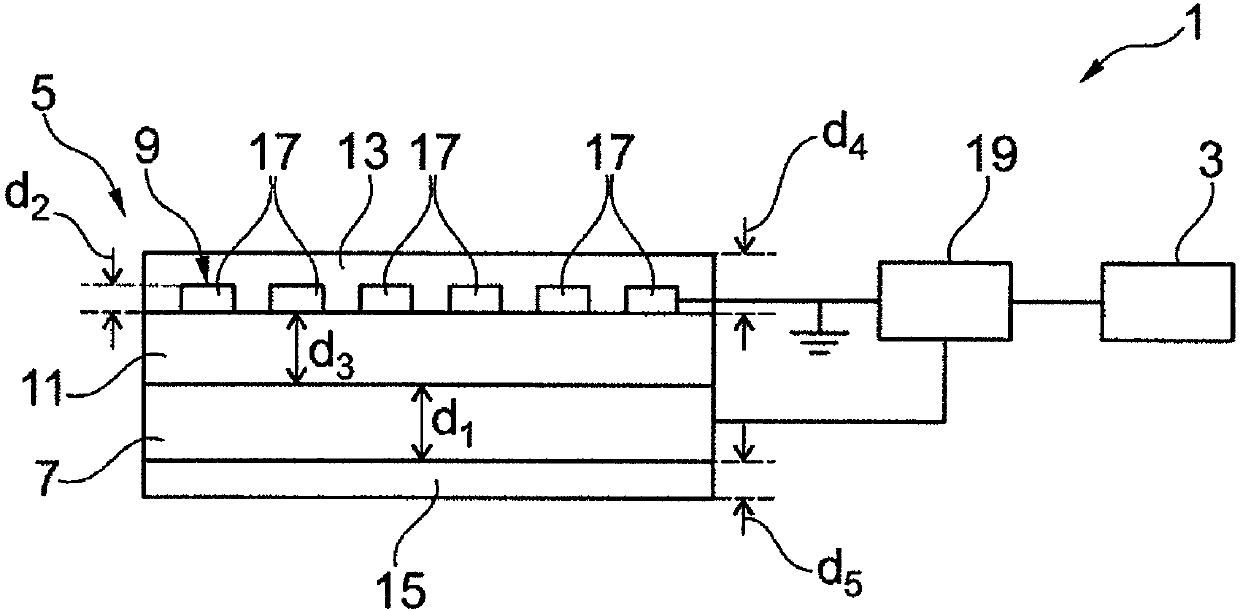
[0080] figure 1 A schematic diagram of an exemplary embodiment of a plasma source 1 arranged to generate a non-thermal plasma is shown. The plasma source 1 has a voltage source 3 electrically connected to an electrode arrangement 5 . As such, the electrode arrangement 5 is arranged to generate an athermal plasma.

[0081] It has a first electrode 7 and a second electrode 9 , between which a dielectric element 11 is arranged such that the two electrodes 7 , 9 are electrically insulated from and spaced apart from each other by the dielectric element 11 . The two electrodes 7 , 9 and the dielectric element 11 form a stack, wherein the dielectric element is arranged on the first electrode 7 and the second electrode 9 is arranged on the dielectric element 11 as seen in the stack direction.

[0082] Viewed in the stacking direction, the first electrode 7 has a first thickness d of at least 10 μm 1 , wherein the second electrode 9 also has a second thickness d of at least 1 μm to ...


PUM

PropertyMeasurementUnit
thicknessaaaaaaaaaa
thicknessaaaaaaaaaa
thicknessaaaaaaaaaa

Abstract

The invention relates to an electrode assembly (5) for generating a non-thermal plasma, comprising a first electrode (7) and a second electrode (9) which are electrically insulated from each other bymeans of a dielectric element (11) and which are arranged at a distance from each other. The first electrode (7) has a thickness of at least 10 [mu]m when seen in the direction of the distance betweenthe electrodes (7, 9), and the second electrode (9) has a thickness of at least 1 [mu]m to maximally 5 [mu]m or a thickness of at least 5 [mu]m to maximally 30 [mu]m when seen in the direction of thedistance between the electrodes (7, 9). The dielectric element (11) has a thickness of at least 10 [mu]m to maximally 250 [mu]m.

Description

technical field [0001] The invention relates to an electrode arrangement and a plasma source for generating a non-thermal plasma, as well as a method for operating the plasma source. Background technique [0002] Electrode arrangements for generating non-thermal plasmas usually have a first electrode and a second electrode, the electrodes being electrically insulated from one another and spatially separated from one another by a dielectric element. Typical uses of such electrode devices or of non-thermal plasmas generated by such electrode devices are in disinfection or sterilization, surface functionalization, and in the field of medicine, especially wound disinfection, wound treatment and healing, treatment of skin allergies, and bacteria , Treatment of viral and fungal skin diseases. It is revealed that the chemical composition of the plasma generated by the electrode arrangement depends largely on the vertical distance from the active surface of the electrode arrangemen...

Claims


Application Information

Patent Timeline
Patent Type & Authority Applications(China)
IPC IPC(8): H05H1/24
CPCH01J37/32532H05H1/2439H05H1/46H01J49/10H05H1/2418
Inventor 格雷戈尔·莫非尔清水铁司李阳方
Owner TERRAPLASMA GMBH
Why Eureka
Try Eureka