Environment-friendly cement foaming material processing device and method

A technology for cement foaming and material processing, applied in cement mixing devices, clay preparation devices, chemical instruments and methods, etc. The effect of structural order

Inactive Publication Date: 2018-03-30
FOSHAN HIGH GRADE ROBOT INTELLIGENT EQUIP CO LTD
4 Cites 1 Cited by

AI-Extracted Technical Summary

Problems solved by technology

[0006] In the process of building construction and home decoration, with the continuous progress of society, people's requirements for various materials are becoming more and more stringent, such as thermal insulation effect, heat insulation effect, hardness, strength, etc., cement foam material is a kind of A kind of material that can meet the needs of modern urban construction. Its processing and manufacturing principle is mainly to mix air with foaming liquid and then mix it with cement...

Abstract

The invention discloses an environment-friendly cement foaming material processing device and method. The device comprises a foaming agent stirring chamber, a blending chamber and a controller. Stirring supports, a discharging pipe and a valve are arranged on the lower portion of the foaming agent stirring chamber. A stirring main shaft and stirring blades are arranged in the middle of the foamingagent stirring chamber. A motor support, a stirring motor and a foaming fluid inlet hopper are arranged on the upper portion of the foaming agent stirring chamber. The controller, a stirring belt pulley, a motor belt pulley and a V-shaped belt are arranged at one side of the foaming agent stirring chamber. The blending chamber is arranged at one side of the discharging pipe. A blending motor, blending supports, a finished product discharging pipe and the valve are arranged on the lower portion of the blending chamber. A blending and stirring main shaft, stirring bars and a blending and feeding hopper are arranged in the middle and on the upper portion of the blending chamber. Air is uniformly led into a foaming agent solution through the blades rotating at a high speed, blended with cement and stirred, the structure is simple, the practicability is high, the whole process is performed in a semi-sealing state, and pollution is almost zero.

Application Domain

Technology Topic

Image

  • Environment-friendly cement foaming material processing device and method
  • Environment-friendly cement foaming material processing device and method
  • Environment-friendly cement foaming material processing device and method

Examples

  • Experimental program(1)

Example Embodiment

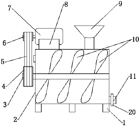
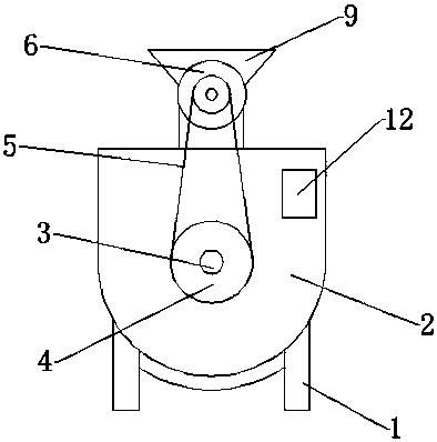
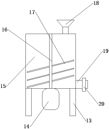
[0025] The present invention will be further explained below in conjunction with the drawings:
[0026] Such as figure 1 , figure 2 with image 3 As shown, an environmentally friendly cement foaming material processing device and processing method include a foaming agent stirring chamber 2, a mixing chamber 15 and a controller 12. Below the foaming agent stirring chamber 2, a stirring support 1, a discharge pipe 11 and The valve 20, the foaming agent stirring chamber 2 is provided with a stirring spindle 3 and a stirring blade 10 in the middle. The stirring spindle 3 drives the stirring blade 10 to rotate at a high speed, exposing the stirring blade 10 to the air, thereby driving the air to mix with the foaming liquid. Foaming agent, a motor support 8, a stirring motor 7 and a foaming liquid feed hopper 9 are arranged above the foaming agent stirring chamber 2, and a controller 12, a stirring pulley 4, and a motor belt are arranged on one side of the foaming agent stirring chamber 2 Wheel 6 and V-belt 5, the stirring motor 7 is directly connected to the stirring spindle 3 through the motor pulley 6 and the stirring pulley 4, in order to provide a higher speed, and a mixing chamber 15 is provided on the side of the discharge pipe 11 15 is mainly to mix the prepared foaming agent with cement to make foamed cement. Below the mixing chamber 15 are provided a mixing motor 14, a mixing support 13, a finished product discharge pipe 19 and a valve 20, and the middle and above the mixing chamber 15 A mixing spindle 16, a mixing rod 17 and a mixing hopper 18 are provided.
[0027] In the above structure, the stirring motor 7 and the mixing motor 14 are activated by the controller 12 to make the equipment enter the working state. The foaming liquid is added to the foaming liquid mixing chamber 2 through the foaming liquid feed hopper 9, and the mixing feed hopper 9 18 Add cement and an appropriate amount of water to the mixing chamber 15, the high-speed rotating mixing blade 10 is exposed in the liquid, and is in contact with the air, and the air is introduced into the foaming liquid. With the progress of the stirring process, the air and foam When the requirements are met, the control valve 20 on the discharge pipe 11 is opened, and the foaming liquid mixed with air is added to the mixing chamber 15 through the mixing hopper 18 through the hydraulic pump. The function of the mixing motor 14 is Next, the stirring rod 17 is driven to rotate to mix the foaming liquid with air and the cement slurry, thereby making the cement foaming material.
[0028] In order to further improve the use function of the environmentally friendly cement foaming material processing device, the foaming agent mixing chamber 2 is fixed above the stirring support 1 by welding, the mixing spindle 3 is rotatably connected to both sides of the foaming agent mixing chamber 2, and the mixing blade 10 is screwed Fixed on the mixing spindle 3, the motor support 8 is fixed above the foaming agent mixing chamber 2 by bolts, the stirring motor 7 is fixed on the motor support 8 by bolts, the foaming liquid feed hopper 9 and the discharge pipe 11 are both welded It is fixed on the foaming agent stirring chamber 2 and connected with the foaming agent stirring chamber 2. The stirring pulley 4 is connected with the stirring spindle 3 through the key, the motor belt 6 is connected with the stirring motor 7 through the key, and the motor pulley 6 is connected with the stirring motor 7 The mixing pulley 4 is connected by the V belt 5, the mixing motor 14 is fixed under the mixing chamber 15 by bolts, the main shaft of the mixing motor 14 and the mixing main shaft 16 are connected by a coupling, and the stirring rod 17 is fixed on the mixing main shaft 16 by welding. , The controller 12 is fixed on one side of the foaming agent stirring chamber 2 by screws, and the stirring motor 7 and the mixing motor 14 are electrically connected to the controller 12.
[0029] The basic principles, main features and advantages of the present invention have been shown and described above. Those skilled in the industry should understand that the present invention is not limited by the foregoing embodiments. The foregoing embodiments and descriptions only illustrate the principles of the present invention. Without departing from the spirit and scope of the present invention, the present invention may have Various changes and improvements, these changes and improvements fall within the scope of the claimed invention. The scope of protection claimed by the present invention is defined by the appended claims and their effects.

PUM

no PUM

Description & Claims & Application Information

We can also present the details of the Description, Claims and Application information to help users get a comprehensive understanding of the technical details of the patent, such as background art, summary of invention, brief description of drawings, description of embodiments, and other original content. On the other hand, users can also determine the specific scope of protection of the technology through the list of claims; as well as understand the changes in the life cycle of the technology with the presentation of the patent timeline. Login to view more.

Similar technology patents

Ash clearing device and method for travelling triboelectric path

PendingCN111957667AAutomatic and efficient dust removalStructure orderDirt cleaningCleaning using gasesPhysicsEngineering
Owner:MCC BAOSTEEL TECH SERVICE

Classified garbage can device

PendingCN110844393AStructure orderPrevent the leakage of rancid gasWaste collection and transferRefuse receptaclesMechanical engineeringRefuse collection
Owner:徐州鸿誉环境科技有限公司

Letter box

Owner:苏州海森伯格环保科技有限公司

Classification and recommendation of technical efficacy words

  • Practical
  • Structure order

Optimization method for spray gun track of spraying robot on irregular polyhedron

ActiveCN102500498APracticalImprove work efficiency and product qualitySpraying apparatusSpecial data processing applicationsComputer Aided DesignParticle swarm algorithm
Owner:JIANGSU NEWBLUE INTELLIGENT EQUIP CO LTD

Special rotary grading machine for pulverized fuel ash

InactiveCN106064150AImprove sorting efficiencyStructure orderGas current separationFly ashPulverized fuel ash
Owner:WUXI HUATONG ELECTRIC POWER EQUIP

Explosion-proof equipment of lithium battery

InactiveCN107017373AAvoid explosion damageStructure orderFinal product manufactureLi-accumulatorsEngineeringAnode
Owner:CHENGDU FEIHANG PEIPENG TECH CO LTD

Material feeding mechanism

InactiveCN102991752AStructure orderImprove efficiencyPackagingManipulatorEngineering
Owner:江阴纳尔捷机器人有限公司

Projection device for visual communication design

ActiveCN110045567AStructure orderEasy to operateProjectorsStands/trestlesEngineeringVisual communication
Owner:XIAN TECHNOLOGICAL UNIV

Classified garbage can device

PendingCN110844393AStructure orderPrevent the leakage of rancid gasWaste collection and transferRefuse receptaclesMechanical engineeringRefuse collection
Owner:徐州鸿誉环境科技有限公司
Why Eureka
Try Eureka