Long-distance point sensing system based on optical fiber random laser

A random laser and sensing system technology, applied in the direction of transmitting sensing components using optical devices, can solve problems such as complex system architecture devices, and achieve the effect of structural orders

Active Publication Date: 2013-10-30
UNIV OF ELECTRONICS SCI & TECH OF CHINA
View PDF2 Cites 8 Cited by
  • Summary
  • Abstract
  • Description
  • Claims
  • Application Information

AI Technical Summary

Problems solved by technology

The above implementation methods generally require complex system architecture and expensive devices

Method used


Image

  • Long-distance point sensing system based on optical fiber random laser
  • Long-distance point sensing system based on optical fiber random laser
  • Long-distance point sensing system based on optical fiber random laser

Examples


Embodiment 1

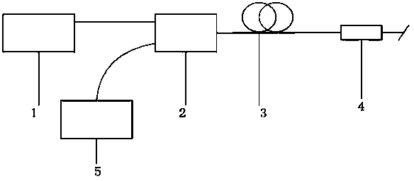
[0017] see figure 1 , a long-distance point sensing system based on fiber random laser, which is a point sensing system based on first-order random laser, the system includes pump laser 1, wavelength division multiplexer 2, long-distance single-mode fiber 3 , the wavelength selection device 4, the preferred fiber Bragg grating (FBG) of the wavelength selection device 4; the pump laser 1 is connected to the 1 port of the wavelength division multiplexer 2, and the common port of the wavelength division multiplexer 2 is connected to the long-distance single One end of the single-mode optical fiber 3, the other end of the long-distance single-mode optical fiber 3 is connected to the wavelength selection device 4, and the 2 ports of the wavelength division multiplexer 2 are connected to the wavelength demodulation module 5, and the wavelength demodulation module 5 can obtain long-distance sensing Detection amount.

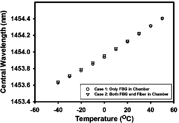
[0018] image 3 It is the temperature response diagram of the FB...

Embodiment 2

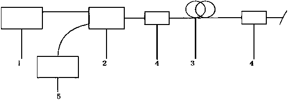
[0021] see figure 2 , a long-distance point sensing system based on fiber optic random laser, which is equivalent to a point sensing system based on second-order random laser, the device includes a pump laser 1, a wavelength division multiplexer 2, and a wavelength selective device 4 , a long-distance single-mode fiber 3, a wavelength selection device 4; the pump laser 1 is connected to port 1 of the wavelength division multiplexer 2, and the common port of the wavelength division multiplexer 2 is first connected to the wavelength selection device 4, and then the wavelength The selection device 4 is connected to one end of the long-distance single-mode fiber 3 , the other end of the long-distance single-mode fiber 3 is connected to the wavelength selection device 4 , and the port 2 of the wavelength division multiplexer 2 is connected to the wavelength demodulation module 5 .

[0022] The detection steps of the long-distance point sensing system based on random laser are: tur...


PUM


Abstract

The invention discloses a long-distance point sensing system based on an optical fiber random laser. The system comprises a pump laser, a wavelength division multiplexer or a coupler, a long-distance single-mode fiber, wavelength selection devices for sensing, a wavelength selection device for improving random laser generation efficiency, and a wavelength demodulation module. The wavelength division multiplexer or the coupler comprises a 1 port, a public port and a 2 port, wherein the pump laser is connected with the 1 port of the wavelength division multiplexer or the coupler; one end of the long-distance single-mode fiber is connected with the public port of the wavelength division multiplexer or the coupler, and the other end of the long-distance single-mode fiber is connected with the plurality of wavelength selection devices for sensing; and the wavelength demodulation module is connected with the 2 port of the wavelength division multiplexer or the coupler. The system is simple in structure; a complex system framework and expensive devices are not needed in the system; during usage, the pump laser is started and the output power of the pump laser is adjusted to an appropriate range, and thus the long-distance sensing detection quantity can be obtained through the wavelength demodulation module.

Description

technical field [0001] The invention relates to the technical field of optical fiber sensing, in particular to a long-distance point sensing system. Background technique [0002] Fiber optic point sensors have many advantages: anti-electromagnetic interference, small size, passive, corrosion-resistant, etc. These characteristics make the fiber optic point sensor have a great range of applications, it can be used in oil wells, natural gas pipelines, tunnels, bridges and other occasions. When long-distance telemetry is required due to objective conditions, such as volcanic eruptions, nuclear radiation and other environmental hazards, or deserts and other inaccessible areas, it is necessary to use various technical means to extract sensing signals remotely. In order to extend the sensing distance, the existing technologies include high-speed frequency-sweeping laser and Raman amplification, active optical fiber remote pumping amplification and other methods. The above impleme...

Claims


Application Information

Patent Timeline
Patent Type & Authority Applications(China)
IPC IPC(8): G01D5/26
Inventor 王子南饶云江姜芸
Owner UNIV OF ELECTRONICS SCI & TECH OF CHINA
Why Eureka
Try Eureka