
Exterior window lintel structure

A technology for lintels and external windows, applied to truss structures, joists, girders, etc., can solve the problems of excessive heat transfer coefficient of external window lintels, reduce heat transfer coefficients, increase construction costs, and facilitate heat preservation energy saving effect

Inactive Publication Date: 2018-03-30
HARBIN INST OF TECH
View PDF12 Cites 0 Cited by
  • Summary
  • Abstract
  • Description
  • Claims
  • Application Information

AI Technical Summary

Problems solved by technology

[0004] The present invention aims to solve the thermal bridge problem caused by the excessive heat transfer coefficient of the outer window lintel, and now provides an outer window lintel structure

Method used


Image

  • Exterior window lintel structure

Examples


specific Embodiment approach 1

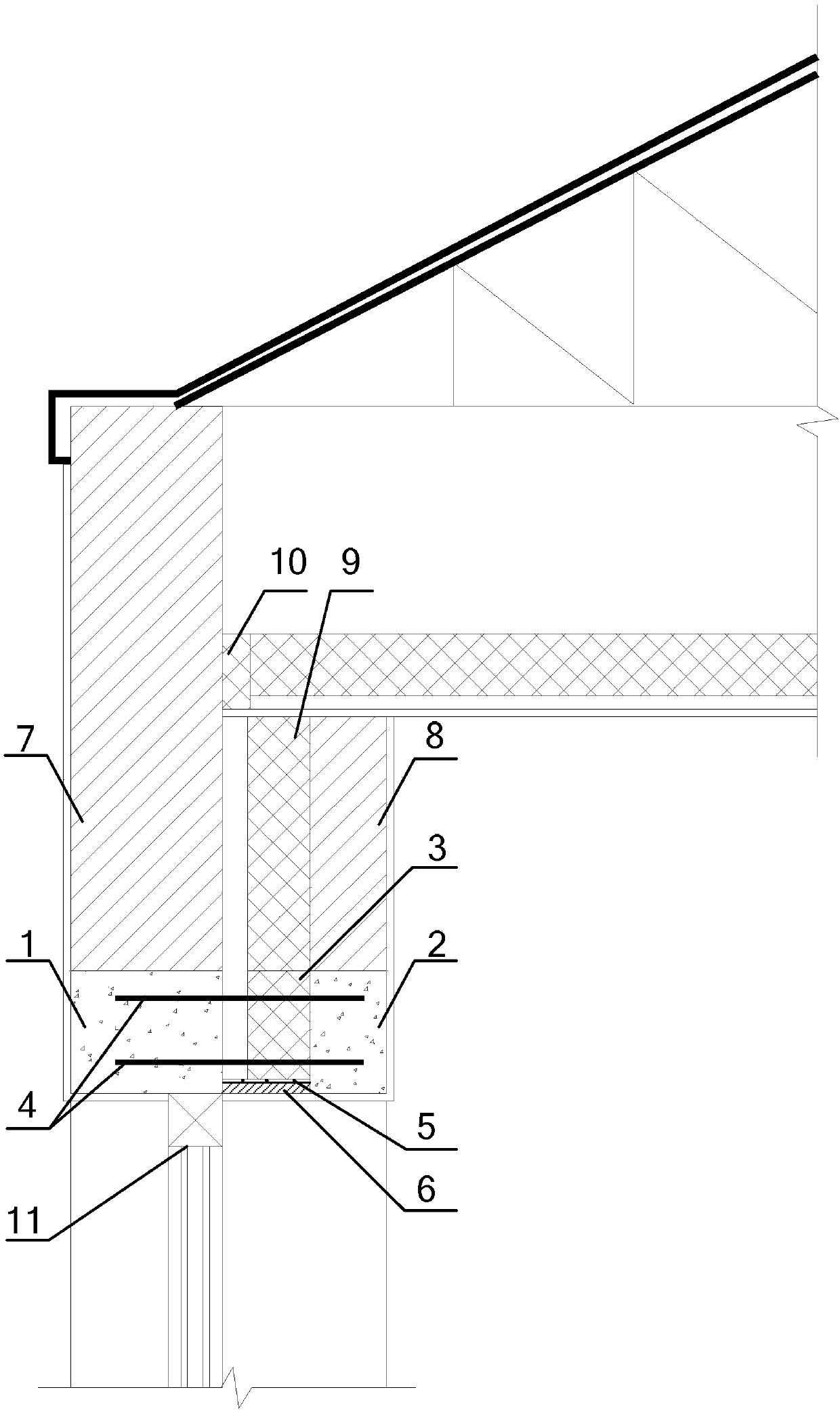
[0014] refer to figure 1 Describe this embodiment in detail, an outer window lintel structure described in this embodiment, the structure includes an outer beam 1, a lintel insulation layer 3 and an inner beam 2;

[0015] The outer beam 1 is fixed between the top of the outer window frame and the outer wall 7, and the thickness is the same as that of the outer wall 7,

[0016] The lintel insulation layer 3 is fixed between the top of the outer window frame and the wall insulation layer 9,

[0017] The inner beam 2 is fixed between the top of the window hole and the inner wall 8, and the thickness is the same as that of the inner wall 8,

[0018] The bottom of the lintel insulation layer 3 is provided with a steel wire mesh 5, and the outer surface of the steel wire mesh 5 is coated with mortar 6,

[0019] The outer girder 1 and the inner girder 2 are connected by two parallel reinforcement bars 4, and the reinforcement bars 4 are arranged horizontally.

[0020] The exterior...

specific Embodiment approach 2

[0021] Specific embodiment 2: This embodiment is to further illustrate a kind of outer window lintel structure described in specific embodiment 1. In this embodiment, when the lintel insulation layer 3 adopts non-hydrophobic thermal insulation materials, in order to avoid heat preservation If the layer is damp, the performance of the thermal insulation material will be reduced. There is a gap between the outer beam 1 and the lintel insulation layer 3. This gap is used as a moisture-proof air interlayer, and the distance between the outer beam 1 and the lintel insulation layer 3 is equal to the wall air space. layer thickness.

specific Embodiment approach 3

[0022] Specific embodiment three: this embodiment is a further description of a kind of exterior window lintel structure described in specific embodiment one. In this embodiment, a roof insulation layer 10 is laid between the outer wall 7 and the shed roof, and the roof insulation Layer 10 has a thickness of 50 mm. Laying the roof insulation layer 10 between the outer wall 7 and the roof can cut off the thermal bridge of this part, further achieving the purpose of insulation.


PUM

PropertyMeasurementUnit
Thicknessaaaaaaaaaa
Diameteraaaaaaaaaa

Abstract

The invention relates to the technical field of window body insulation structure construction, and provides an exterior window lintel structure. The exterior window lintel structure is to solve the thermal bridge problem caused by an excessive heat transfer coefficient of an exterior window lintel. The exterior window lintel structure includes an outer beam, a lintel insulating layer and an innerbeam which are arranged in sequence from outside to inside; the thickness of the outer beam is the same as the thickness of an outer wall, and the thickness of the inner beam is the same as the thickness of an inner wall. The bottom of the lintel insulating layer is provided with a steel wire mesh; the outer surface of the steel wire mesh is coated with mortar. The outer beam and the inner beam are connected by two parallel reinforcing steel bars in a pulling mode, and the reinforcing steel bars are horizontally arranged. The exterior window lintel structure is fixed between the top portion ofan exterior window frame and a wall body. The exterior window lintel structure is suitable for the construction of demonstration houses in villages and towns in severe cold regions, and is particularly suitable for exterior window lintels of intermittently heating houses in villages and towns in severe cold regions.

Description

technical field [0001] The invention belongs to the technical field of window insulation structure construction. Background technique [0002] Villages and towns in severe cold areas usually have an independent heating system. For villages and towns that use kang as heating method for intermittent heating, lightweight and high-efficiency thermal insulation materials with small heat storage coefficients should be installed inside the outer wall structure layer to reduce the attenuation of the enclosure structure. degree, arrange the load-bearing wall on the side close to the outdoor. [0003] Considering the production and living habits of village and town dwellings, farm tools are often piled up indoors or ornaments are placed on the inner surface of the wall. Therefore, a protective wall is added inside the insulation layer to form a sandwich insulation structure. However, since the insulation material is arranged on the inside, it cannot cover the entire wall structure. ...

Claims


Application Information

Patent Timeline
IPC IPC(8): E04C3/20E04B1/76
CPCE04B1/76E04C3/20Y02A30/00Y02B30/90
Inventor 金虹邵腾
Owner HARBIN INST OF TECH
Learn More