Dust removal sedimentation device

A technology of sedimentation device and dust removal bucket, which is applied in the direction of filtration circuit, use of liquid separation agent, filtration separation, etc., can solve the problems of transformation, reduction of dust removal effect, environmental pollution, etc., to ensure dust removal effect, reduce water consumption, and prevent waste Effect

Active Publication Date: 2018-04-06
遵义双河生物燃料科技有限公司
View PDF6 Cites 7 Cited by
  • Summary
  • Abstract
  • Description
  • Claims
  • Application Information

AI Technical Summary

Problems solved by technology

[0003] However, in the existing sedimentation tank, various forms of baffles are installed in the settling chamber, and the dust-laden exhaust gas impacts on the baffle, and the direction of the airflow changes sharply. With the help of the inertial force of the small particles of dust itself, the small particles of dust are separated from the airflow. , submerged in water
[0004] There are the following technical problems in the prior art: 1. The bottom surface of the water retaining plate is easy to leave dirt. If this happens for a long time, the effect of dust removal in the later stage will be reduced; 2. The water in the sedimentation tank will become sewage, which cannot be recycled and will cause environmental pollution.
That is to say, the existing technology cannot solve the sewage treatment problem of the sedimentation tank

Method used


Image

  • Dust removal sedimentation device
  • Dust removal sedimentation device
  • Dust removal sedimentation device

Examples


Embodiment Construction

[0028] The present invention will be described in further detail below by means of specific embodiments:

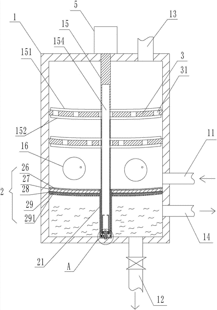
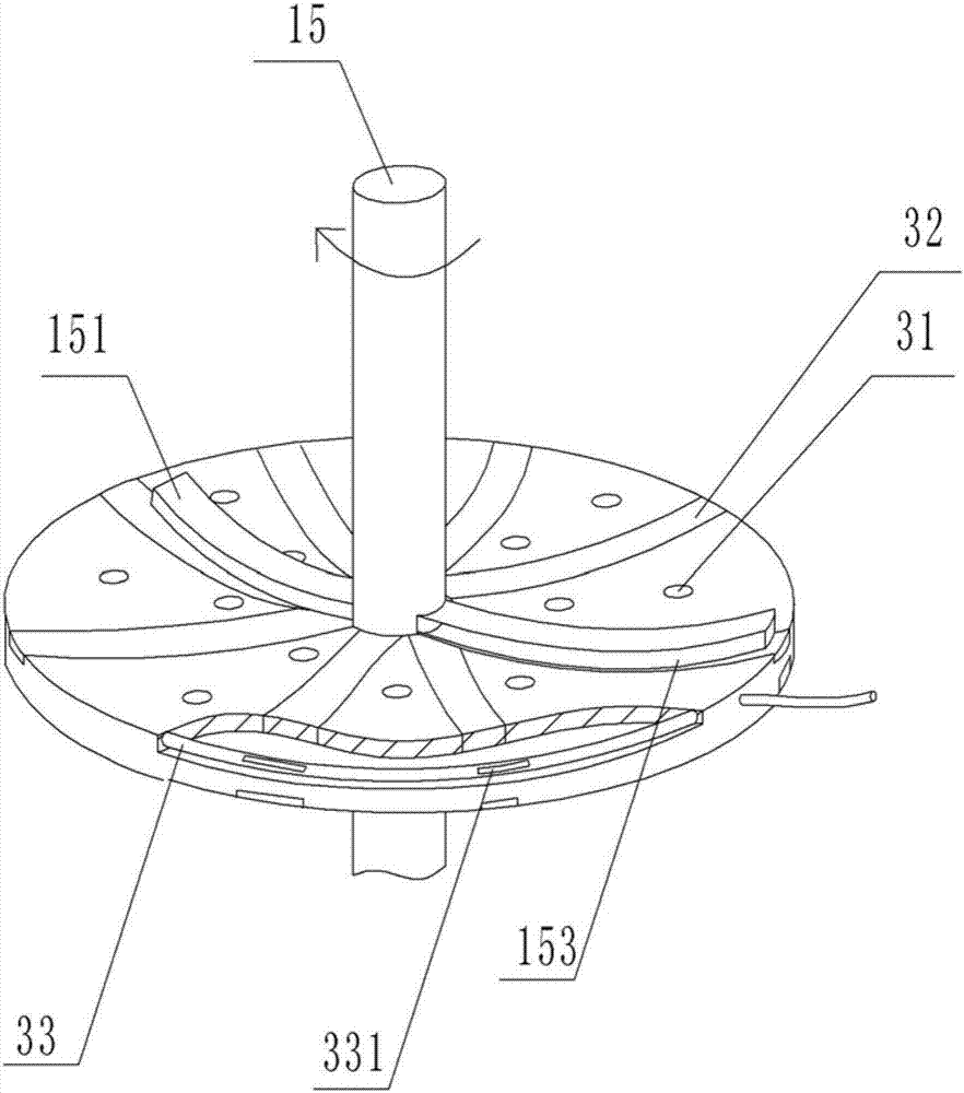
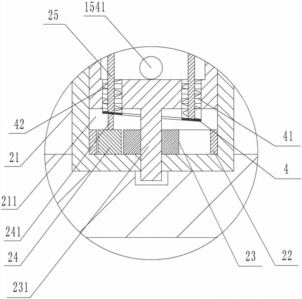
[0029]The reference signs in the accompanying drawings of the specification include: dust removal bucket 1, air intake pipe 11, sewage outlet pipe 12, exhaust pipe 13, clear liquid discharge pipe 14, rotating shaft 15, upper scraping strip 151, lower scraping strip 152, scraping groove 153 , sewage cavity 154, discharge port 1541, cleaning port 16, filter plate 2, support column 21, power chamber 211, inner ring gear 22, driving gear 23, rotating rod 231, driven gear 24, pushing rod 241, stirring rod 25 , carbon layer 26, sand layer 27, gravel layer 28, cotton cloth layer 29, filter screen plate 291, dust removal plate 3, air hole 31, water absorption layer 32, annular water pipe 33, insertion port 331, fixed ring 4, rubber cover 41, spring 42, motor 5.

[0030] Such as figure 1 , figure 2 and image 3 As shown, the dust removal and precipitation device includes a du...


PUM


Abstract

The invention relates to the technical field of apparatuses for discharging solid components in exhaust gas, and especially provides a dust removal sedimentation device. The device includes a dust removal barrel on which an air pipe, a sewage draining pipe, an exhaust pipe and a clear liquid discharge pipe are disposed. A rotary shaft, which is driven by a power device, is arranged in the dust removal barrel. A filter plate and a dust removal plate are arranged in the dust removal barrel. A support column is fixedly connected to the bottom surface of the filter plate. A rotary chamber is formed in the support column. The rotary shaft is rotationally connected to the chamber wall of the rotary chamber. Bar-shaped grooves, in which water absorption layers are disposed, are arranged in both the upper and the lower surfaces of the dust removal plate. An annular water pipe is arranged in the dust removal plate. An upper scraping bar and a lower scraping bar are fixedly connected to the rotary shaft, wherein scraping grooves are arranged in the side walls of the upper scraping bar and the lower scraping bar. A sewage draining chamber is located inside the rotary shaft, wherein a discharge outlet is formed in the chamber wall of the sewage draining chamber. A stirring structure is arranged in the sewage draining chamber. A stirring hole is formed in the bottom surface of the rotary shaft. An elastic structure is arranged inside the stirring hole. The dust removal sedimentation device can avoid residual dirt on a water baffle, and also can precipitate wastewater.

Description

technical field [0001] The invention relates to the technical field of devices for discharging solid components in exhaust gas, in particular to a dust removal and sedimentation device. Background technique [0002] "Biomass molding fuel" is made of agricultural and forestry residues as the main raw material. After screening, drying, cyclone separation, molding and granulation, cooling, screening, and finished products, it is finally made into a molding environmentally friendly fuel with high calorific value and sufficient combustion. . Among them, a large amount of dusty waste gas is likely to be generated during drying and cyclone separation. The dusty waste gas is usually removed by a bag filter to remove large particles of dust in the dusty waste gas, and then the remaining dusty waste gas is discharged into the sedimentation tank to remove small particles of dust. The air after two dust removal treatments can meet the emission standard. [0003] However, in the existi...

Claims


Application Information

Patent Timeline
Patent Type & Authority Applications(China)
IPC IPC(8): B01D47/02B01D36/04
Inventor 刘福基
Owner 遵义双河生物燃料科技有限公司
Why Eureka
Try Eureka