Ammonia-nitrogen mixing device for ammonia injection system of thermopower boiler

A mixing device and boiler technology, which is applied in the direction of mixers, mixing methods, gas and gas/steam mixing, etc., can solve the problems of uneven distribution of ammonia nitrogen molar ratio, improve the mixing effect, reduce the flow area, and enhance the mixing effect Effect

Pending Publication Date: 2018-04-06
SHANXI UNIV
View PDF12 Cites 2 Cited by
  • Summary
  • Abstract
  • Description
  • Claims
  • Application Information

AI Technical Summary

Problems solved by technology

[0004] The purpose of the present invention is to solve the problem of uneven distribution of ammonia nitrogen molar ratio in flue gas at the catalyst inlet of SCR denitrification system of large thermal power boiler

Method used


Image

  • Ammonia-nitrogen mixing device for ammonia injection system of thermopower boiler
  • Ammonia-nitrogen mixing device for ammonia injection system of thermopower boiler
  • Ammonia-nitrogen mixing device for ammonia injection system of thermopower boiler

Examples


Embodiment Construction

[0026] The principles and features of the present invention are described below in conjunction with the accompanying drawings, and the examples given are only used to explain the present invention, and are not intended to limit the scope of the present invention.

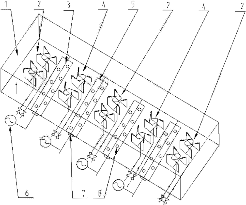
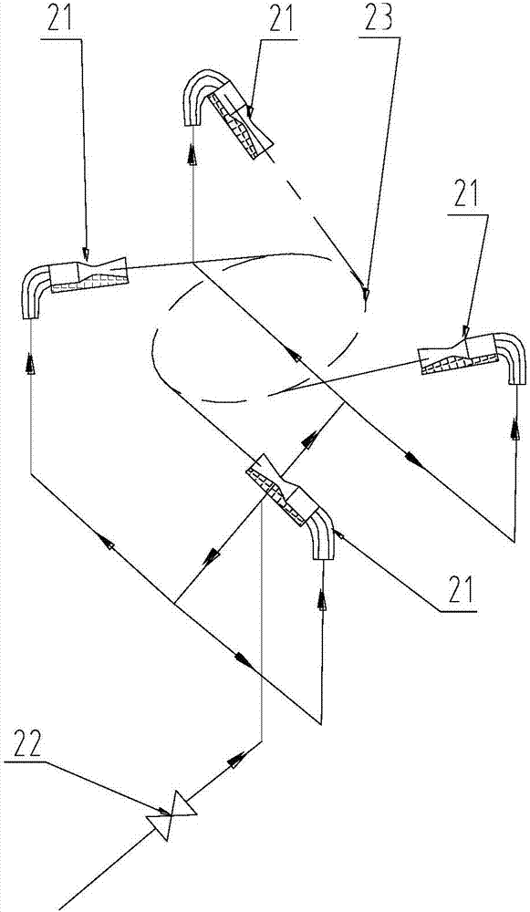
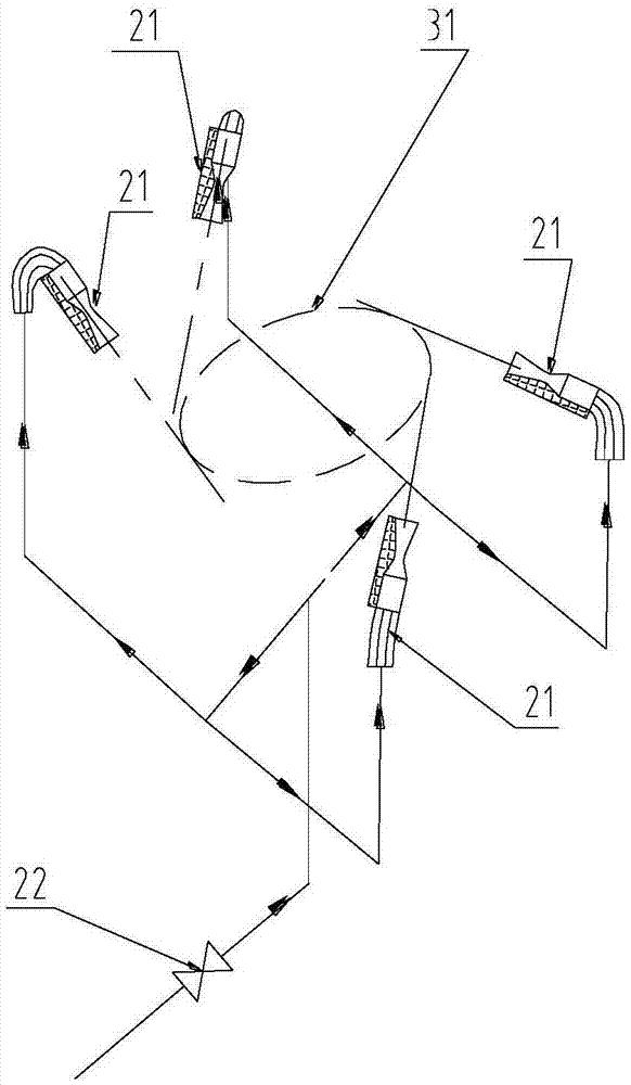
[0027] Such as figure 1 As shown, an ammonia nitrogen mixing device used in the ammonia injection system of a thermal power boiler in this embodiment includes a clockwise mixer unit group 2, a counterclockwise mixer unit group 4, an air distribution plate 5, a motor 6 and a sealing device 7 ;Such as figure 2 As shown, the clockwise mixer unit group 2 includes two clockwise mixers, and the clockwise mixer is composed of 4 nozzle assemblies 21, and the injection directions of the 4 nozzle assemblies 21 form an imaginary cut in the clockwise direction. Circle 23, the inlets of 4 nozzle assemblies 21 are connected with ammonia main pipe by the pipe that is provided with regulating valve 22; image 3 As shown, the cou...


PUM


Abstract

The invention particularly relates to an ammonia-nitrogen mixing device for an ammonia injection system of a thermopower boiler. According to the ammonia-nitrogen mixing device, the problem of non-uniform ammonia-nitrogen mole ratio in flue gas at a catalyst inlet of an SCR (Selective Catalytic Reduction) denitrification system of a large-sized thermopower boiler is solved. The ammonia-nitrogen mixing device comprises clockwise mixer unit groups, anticlockwise mixer unit groups, air distribution plates, motors, sealing devices and the like; laval nozzles are used for generating supersonic ammonia current for strongly entraining surrounding flue gas; ammonia gas nozzles are distributed in a corner tangential mode to form a strongly-rotating vortex region for intensifying the mixing of the ammonia gas and the flue gas. According to the ammonia-nitrogen mixing device disclosed by the invention, by adopting the porous air distribution plates, relative speed difference of the ammonia gas and the flue gas is improved, and the problem that the ammonia gas and the flue gas are difficult to be mixed when the boiler operates at a low load is solved; relative deviation of the ammonia-nitrogenmole ratio in the flue gas at a catalyst layer inlet along the width direction can be smaller than 5 percent, and relative deviation of the ammonia-nitrogen mole ratio along the depth direction is smaller than 3 percent.

Description

technical field [0001] The invention belongs to the field of SCR denitrification of large thermal power boilers, and in particular relates to an ammonia nitrogen mixing device used in an ammonia injection system of a thermal power boiler. Background technique [0002] During the actual operation of the SCR denitrification system of thermal power coal-fired boilers in my country, there is a problem of uneven mixing of ammonia gas and flue gas before the inlet of the catalyst layer, especially when the boiler is operating at low load, the flow rate of flue gas in the flue is low, and the turbulence intensity is insufficient , the ammonia gas flowing out of the nozzle cannot diffuse rapidly, so the ammonia-nitrogen molar ratio in the flue gas is unbalanced, resulting in high NOx content or high ammonia escape concentration in the flue gas at the outlet of the catalyst layer. [0003] In order to solve this problem, the Chinese patent with the authorized notification number CN202...

Claims


Application Information

Patent Timeline
Patent Type & Authority Applications(China)
IPC IPC(8): B01D53/86B01D53/56B01D53/76B01F3/02B01F13/10B01F23/10
CPCB01D53/76B01D53/8625B01D53/8631B01D2251/2062B01D2258/0283B01F23/10B01F33/811
Inventor 闫高程
Owner SHANXI UNIV
Why Eureka
Try Eureka