
Laser machining equipment for parallel machining

A laser processing and equipment technology, applied in laser welding equipment, metal processing equipment, welding equipment, etc., can solve the problems of low processing efficiency and unsuitable processing of conical focused beams, and achieve the effect of improving laser processing efficiency

Inactive Publication Date: 2018-04-06
INNO LASER TECH CORP LTD +1
View PDF16 Cites 11 Cited by
  • Summary
  • Abstract
  • Description
  • Claims
  • Application Information

AI Technical Summary

Problems solved by technology

[0005] For this reason, the technical problem to be solved by the present invention is that the conical focused beam produced by traditional lasers has low processing efficiency and is not suitable for processing large-format materials, so a laser processing equipment for parallel processing with high processing efficiency is proposed

Method used


Image

  • Laser machining equipment for parallel machining
  • Laser machining equipment for parallel machining

Examples


Embodiment

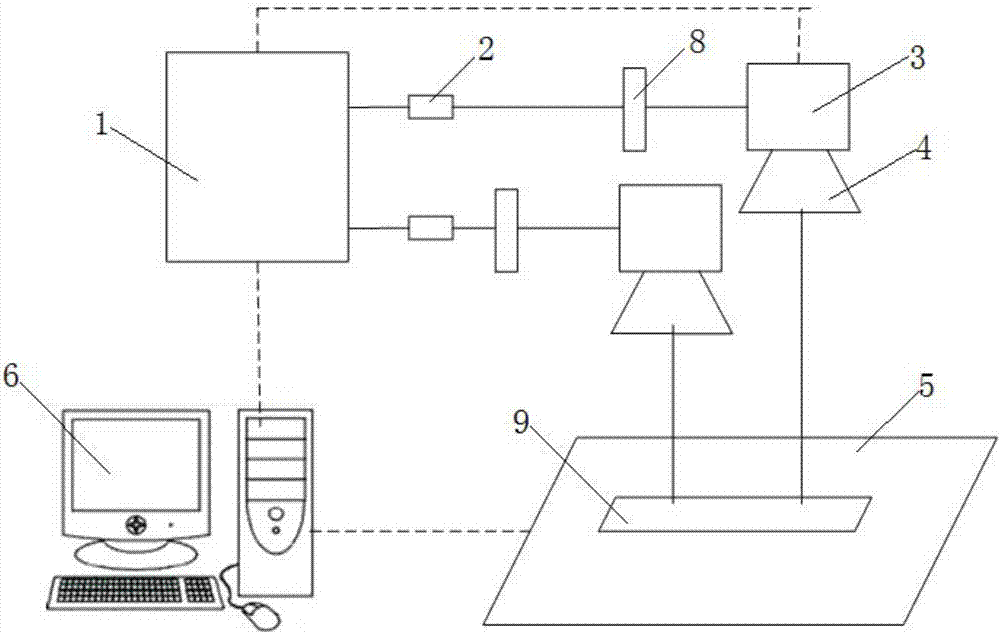
[0024] This embodiment provides a laser processing equipment for parallel processing, which includes a multi-beam laser 1 sequentially arranged along the optical path, a beam expander 2, a vibrating mirror 3 and a lens 4, and the light exit side of the lens 4 is provided with a The processing platform 5 that carries and moves the element 9 to be processed in the X-Y direction also includes a control mechanism 6 for controlling the multi-beam laser 1 and the vibrating mirror 3. The control mechanism 6 is a computer, and the multi-beam laser 1 is a multi-beam laser. One-way solid-state laser, as shown in the figure, it can produce multiple laser beams, the beam expander 2 is set in one-to-one correspondence with the multiple laser light paths generated by the laser, and each beam expander 2 is equipped with a vibrating mirror 3 correspondingly, each A lens 4 is correspondingly arranged behind each vibrating mirror 3 .

[0025] Wherein, the beam expander 2 is a beam expander, whi...

Embodiment 2

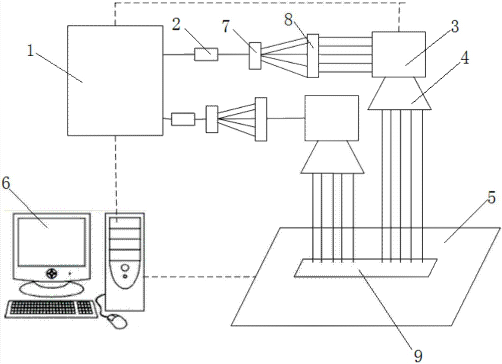
[0029] This embodiment provides a laser processing equipment for parallel processing, which includes a multi-beam laser 1 sequentially arranged along the optical path, a beam expander 2, a vibrating mirror 3 and a lens 4, and the light exit side of the lens 4 is provided with a The processing platform 5 that carries and moves the element 9 to be processed in the X-Y direction also includes a control mechanism 6 for controlling the multi-beam laser 1 and the vibrating mirror 3. The control mechanism 6 is a computer, and the multi-beam laser 1 is a multi-beam laser. One-way solid-state lasers can generate multiple laser beams. The beam expander 2 is provided in one-to-one correspondence with multiple laser light paths generated by the laser, and each beam expander 2 is followed by a vibrating mirror 3 , and each vibrating mirror 3 is followed by a lens 4 correspondingly.

[0030] Wherein, the beam expander 2 is a beam expander, which is used to expand the laser beam generated by...


PUM


Abstract

The invention discloses laser machining equipment for parallel machining. The laser machining equipment comprises a multi-beam output laser device, a beam expanding device, a galvanometer and a lens,all of which are sequentially arranged. The laser machining equipment further comprises a control mechanism for controlling the laser device and the galvanometer. The beam expanding device, the galvanometer and the lens correspond to beams generated by the multi-beam laser device in a one-to-one manner. The laser device emits the multi-beam laser, the output beams are independent of one another, parameters of the output beams can be respectively set and are independent of one another, and the beams sequentially pass through the beam expanding device, the galvanometer and the lens correspondingto the beams and irradiate to the product surface for laser machining. The galvanometer can arrange to-be-machined patterns in a zoned manner according to the characteristics of the machined patterns. The machining equipment can generate multiple parallel laser machining beams at the same time, parallel machining can be conducted on to-be-machined workpieces, the laser machining equipment is suitable for large-breadth material cutting or groove carving or drilling or marking operation, the laser machining efficiency is improved, and the large-area laser machining operation can be achieved.

Description

technical field [0001] The invention belongs to the technical field of laser processing, and in particular relates to a laser processing device for parallel processing. Background technique [0002] Laser processing technology is a processing technology that uses the characteristics of the interaction between laser beams and substances to cut, weld, surface treat, drill and micro-machining materials (metal or non-metal). It is an advanced manufacturing technology. It has been widely used in important fields of the national economy such as automobiles, electronic appliances, aviation, metallurgy, and machinery manufacturing, and has improved product quality and automation. It is a pollution-free and less consumable processing technology. [0003] Laser processing utilizes laser energy to reach a high energy density at the focus point after being focused by a lens, forming a photothermal effect to process materials. Laser processing equipment is one of the key technical equip...

Claims


Application Information

Patent Timeline
Patent Type & Authority Applications(China)
IPC IPC(8): B23K26/00B23K26/067B23K26/064
CPCB23K26/00B23K26/0648B23K26/067
Inventor 赵晓杰陶沙秦国双
Owner INNO LASER TECH CORP LTD
Learn More