Automatic magnetic steel drilling machine

A technology of magnetic steel and countersunk hole, applied in the direction of boring/drilling, drilling/drilling equipment, metal processing, etc., can solve the problems of low processing efficiency, high labor intensity, inclined drilling, etc., to improve processing efficiency , Improve the processing quality, the effect of stable feed

Pending Publication Date: 2018-04-06
宁波市涵鹏机械制造有限公司
View PDF0 Cites 3 Cited by
  • Summary
  • Abstract
  • Description
  • Claims
  • Application Information

AI Technical Summary

Problems solved by technology

[0002] Due to product demand, some magnetic steel needs to be drilled in the center. At first, this kind of drilling was done manually on the drilling machine one by one. The proficiency of the workers is different, and the quality of the products is also uneven.
There is also a certain risk of accidents in manually operating the drilling machine
[0003] With the continuous development of mechanical processing automation, mechanical equipment gradually replaces manual labor to complete some machining, and automatic sinking machines have also emerged as the times require. Automatic sinking machines generally transport the raw materials that need to be prepared to the bottom of the punching machine by the feeding mechanism. , after the hole is punched by the punching machine, the product is removed by the blanking mechanism; but because the existing automatic sinking machine cannot guarantee the centering of the product: first, the center of the product cannot be kept in a straight line with the center of the drill bit First, secondly, the debris generated after drilling remains on the operation platform. When the subsequent products are moved to the operation platform, the debris under the bottom makes it impossible to place them horizontally, which will cause the drilling to tilt; the above two The existence of the main problem leads to a high defective rate of the product, so its structure needs to be further improved

Method used


Image

  • Automatic magnetic steel drilling machine
  • Automatic magnetic steel drilling machine
  • Automatic magnetic steel drilling machine

Examples


Embodiment Construction

[0021] The present invention will be further described in detail below in conjunction with the accompanying drawings and embodiments.

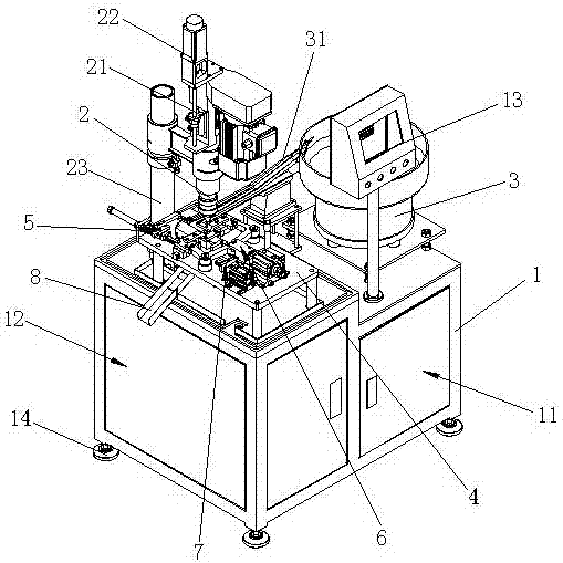
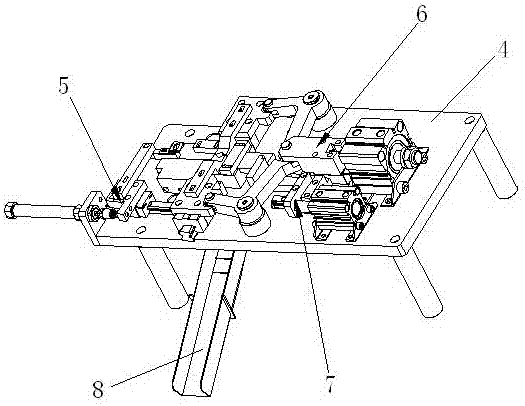
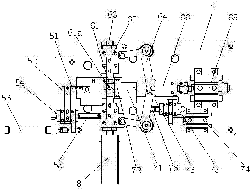
[0022] Such as Figure 1 to Figure 3 Shown is the structural representation of the present invention,

[0023] The reference signs are: frame 1, power distribution cabinet 11, water tank cabinet 12, console 13, support feet 14, drilling rig 2, ball screw 21, servo motor 22, column 23, vibration plate 3, direct vibration Slideway 31, bracket 4, feeding mechanism 5, feeding push block 51, feeding connecting rod 52, feeding cylinder 53, feeding slider 54, feeding slide rail 55, workpiece clamping mechanism 6, clamping block 61 , V-shaped groove 61a, clamping slider 62, clamping slide rail 63, connecting rod 64, clamping cylinder 65, connecting block 66, blanking mechanism 7, slide plate 71, baffle plate 72, blanking connecting rod 73, Blanking cylinder 74, blanking slide block 75, blanking slide rail 76, blanking slideway 8.

[0024] Such as ...


PUM


Abstract

The invention discloses an automatic magnetic steel countersinking machine, in which a power distribution box cabinet and a water tank cabinet are arranged in the frame, a console and a drilling machine are arranged on the frame, and a vibrating plate is arranged on the frame, and the vibrating plate and the direct The entrance of the vibration slideway is connected, and a bracket is fixed on the frame. The bracket is equipped with a feeding mechanism, a workpiece clamping mechanism and a material unloading mechanism. The two clamping blocks of the workpiece clamping mechanism are set under the drilling rig, and the ends of the clamping blocks are respectively provided with V-shaped grooves. The slide plate of the unloading mechanism is set under the clamping block. It goes through the baffle and extends under the clamping block. There is a feeding port under the clamping block on the bracket, and a feeding slideway is fixed on the frame. The inlet of the feeding slideway is located below the feeding port. The rod is connected to the servo motor. The utility model has the advantages that the structure is reasonable, and the automatic centering of the magnetic steel and the automatic cleaning of debris can be realized.

Description

technical field [0001] The invention relates to the technical field of magnetic steel processing, in particular to an automatic magnetic steel sinking machine. Background technique [0002] Due to product demand, some magnetic steel needs to be drilled in the center. At first, this kind of drilling was done manually on the drilling machine one by one. The proficiency of workers is different, and the quality of products is also uneven. There is also a certain risk of accidents in manually operating the drilling machine. [0003] With the continuous development of mechanical processing automation, mechanical equipment gradually replaces manual labor to complete some machining, and automatic sinking machines have also emerged as the times require. Automatic sinking machines generally transport the raw materials that need to be prepared to the bottom of the punching machine by the feeding mechanism. , after the hole is punched by the punching machine, the product is removed by...

Claims


Application Information

Patent Timeline
Patent Type & Authority Applications(China)
IPC IPC(8): B23Q7/14B23B39/00
CPCB23Q7/1457B23B39/00B23Q7/1494
Inventor 陈聪文
Owner 宁波市涵鹏机械制造有限公司
Why Eureka
Try Eureka