Floating LNG production platform

A production platform and floating technology, applied to floating buildings, ships, etc., can solve the problems of ineffective development of offshore natural gas, insufficient technical solutions, high cost, etc., to achieve simple structure, stable operation of devices, and reduced installation and construction cost effect

Pending Publication Date: 2018-04-06
WISON NANTONG HEAVY IND
View PDF1 Cites 3 Cited by
  • Summary
  • Abstract
  • Description
  • Claims
  • Application Information

AI Technical Summary

Problems solved by technology

However, if the natural gas field is located in the far sea, due to the technical limitations of natural gas development and the huge investment in natural gas development engineering facilities such as underwater production systems and submarine pipelines, the natural gas in the far sea cannot be effectively developed
[0003] The existing floating LNG production device mainly adopts the hull structure, which is fixed by a system such as single point mooring, which is usually expensive. Chinese patent CN104608880A discloses a large-scale floating LNG production, storage and unloading device, which includes a hull and a hull deck. FLNG topside facilities on the ship; the hull is arranged in turn from the bow to the stern fore peak tank, inner turret single point tank, LNG tank, LPG tank, condensate oil tank, slop tank, fresh water tank, diesel tank and stern peak tank ;
[0004] However, there are still deficiencies in this technical solution

Method used


Image

  • Floating LNG production platform
  • Floating LNG production platform

Examples


Embodiment Construction

[0021] The present invention is described in further detail now in conjunction with accompanying drawing. These drawings are all simplified schematic diagrams, which only illustrate the basic structure of the present invention in a schematic manner, so they only show the configurations related to the present invention.

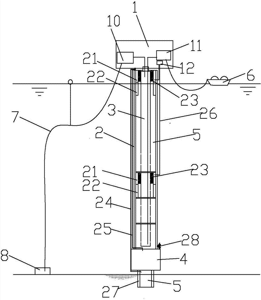
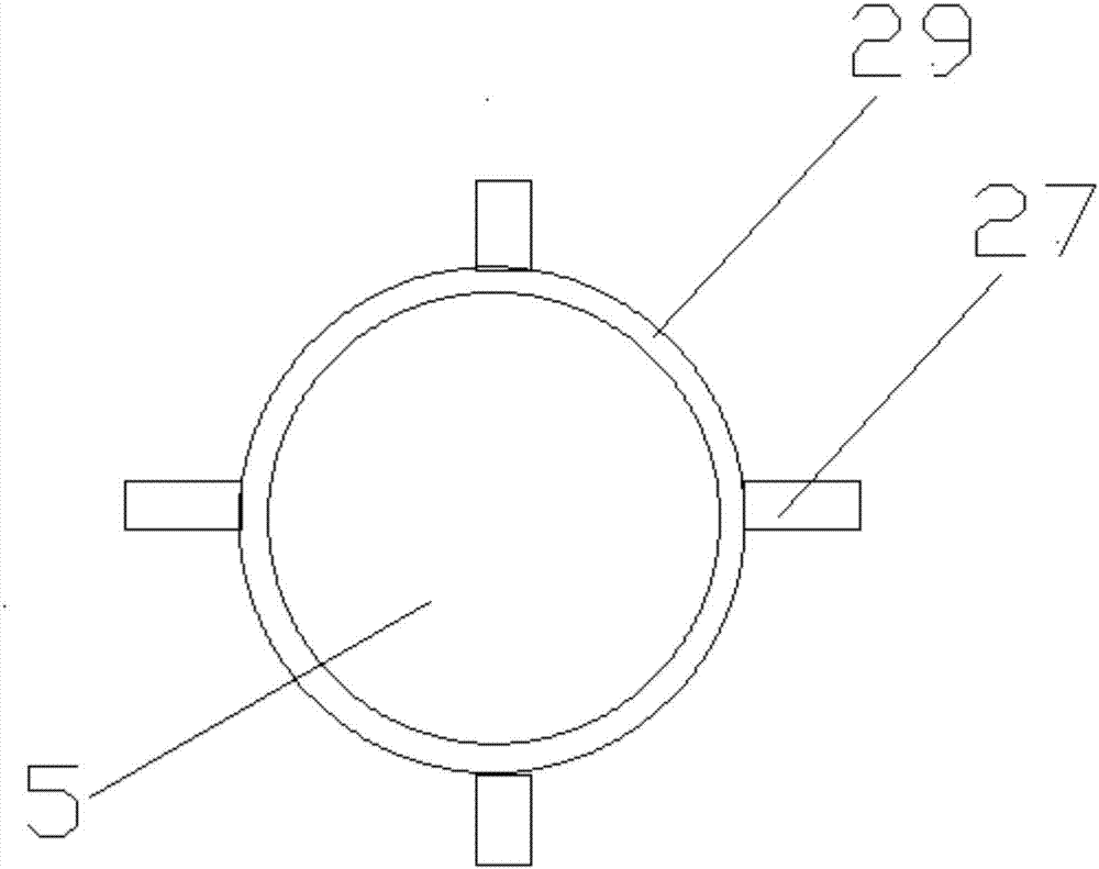
[0022] Such as Figure 1-Figure 2 Shown is a specific embodiment of a floating LNG production platform of the present invention, a floating LNG production platform comprising an upper module 1, a floating body 2 of a hollow structure, a fixed gravity cabin 4 fixedly connected to the bottom of the floating body 2, and The suction pile 5 fixedly connected with the fixed gravity chamber 4, the LNG liquid cargo tank 3 is arranged in the hollow part of the floating body 2, and a plurality of adjustable buoyancy chambers 21, fixed buoyancy chamber 22 and limit device 23 are arranged on the bulkhead of the floating body 2 , the adjustable buoyancy chamber 21, the fi...


PUM


Abstract

A floating LNG production platform comprises an upper module 1, a floating body 2, a fixed gravity tank 4 and a suction pile 5, wherein the floating body 2 has a hollow structure; the fixed gravity tank 4 is fixedly connected with the lower part of the floating body 2; and the suction pile 5 is fixedly connected with the fixed gravity tank 4. An LNG liquid cargo compartment 3 is arranged in the hollow part of the floating body 2; a plurality of adjustable buoyancy tanks 21, a fixed buoyancy tank 21 and a limiting device 23 are arranged on the tank wall of the floating body 2; the adjustable buoyancy tanks 21, the fixed buoyancy tank 21 and the limiting device 23 are annular chambers and arranged in a concentric manner; the suction pile 5 is a cylindrical structure with the closed upper endand the open lower end; the fixed gravity tank 4 is in communication with a mortar pump inlet pipe 25; an exhaust port 28 is formed in the fixed gravity tank 4; the upper module 1 comprises an LNG production unit 10, an LNG unloading unit 11 and a ballast water control unit 12; and the LNG production unit 10 receives raw material natural gas, which is transmitted by a seafloor natural gas wellhead unit 8, through a seafloor hose 7. The floating LNG production platform has the advantages that the floating body can be automatically righted because the floating body is towed to the site in a wetmanner; the floating body is convenient and safe to transport and mount; the upper module is mounted without the coordination of a large floating crane; equipment such as a mooring system is not needed; the structure is simplified; and the mounting and building cost is reduced.

Description

technical field [0001] The invention belongs to the technical field of ocean engineering, and in particular relates to a floating LNG production platform. Background technique [0002] With the growing demand for clean energy natural gas, the development of offshore natural gas resources has become a hot spot in the development of offshore oil and gas resources. The traditional offshore natural gas development model is to use underwater production systems or offshore platforms to transport the extracted natural gas to land terminals through submarine pipelines, and then generally use two methods to transport natural gas: the first is to use pipelines and other facilities to directly send it to users; the second One is to build a natural gas liquefaction plant at a land terminal, transport the natural gas to the LNG gasification terminal near the user after liquefaction, and provide it to the user after gasification. However, if the natural gas field is located in the far se...

Claims


Application Information

Patent Timeline
IPC IPC(8): B63B35/44
CPCB63B35/44B63B2035/4473
Inventor 周建伟袁辉黎丽葛晓强沈建荣
Owner WISON NANTONG HEAVY IND
Why Eureka
Try Eureka