Supercharge Your Innovation With Domain-Expert AI Agents!

Three-phase metering device and method for high-water-content low-yield oil well output liquid

A technology of metering device and oil well, which is used in surveying, earth-moving drilling, wellbore/well components, etc., can solve the problems of affecting the metering accuracy, large metering error, and limited field promotion, and achieves the goal of reducing the separation device and ensuring the accuracy. Effect

Active Publication Date: 2018-04-06
CHINA PETROLEUM & CHEM CORP +1
View PDF20 Cites 6 Cited by
  • Summary
  • Abstract
  • Description
  • Claims
  • Application Information

AI Technical Summary

Problems solved by technology

On this basis, researchers use phase separation technology, such as Chinese patent ZL98113068.2, which uses a partial separation method to reduce the size of the separator, but does not completely separate all three-phase flow into single-phase flow, which affects the measurement accuracy
U.S. Patent No. 6,128,962 also adopts a similar split-phase-separation measurement method, but when the flow rate of the liquid phase or the gas phase in the two-phase flow is very small (low gas content or high water content), through the split flow, from the separator The outflowing gas phase or oil phase flow rate is even smaller, which cannot represent the whole, resulting in large measurement errors
In recent years, with the progress of relevant research work, new technologies for multiphase detection have emerged, mainly using radioactive online testing methods, and also using electrical or magnetic methods for online measurement, but due to radioactivity, the price is high , Difficult to maintain, restricted on-site promotion

Method used


Image

  • Three-phase metering device and method for high-water-content low-yield oil well output liquid
  • Three-phase metering device and method for high-water-content low-yield oil well output liquid
  • Three-phase metering device and method for high-water-content low-yield oil well output liquid

Examples


Embodiment 1

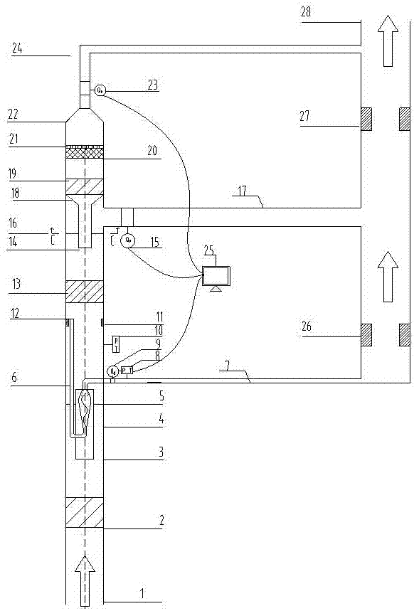
[0043] The oil well produced liquid flows into the oil well oil, gas and water three-phase automatic metering system of the present invention through the vertically installed liquid production inlet section 1. After the produced liquid flows through the cyclone device 2, the inflow is rectified into a gas core and an oil-water mixture. The outer ring adheres to the wall, and the gas core is taken out by the gas core sampling pipe 3 which is placed in the center of the pipeline for sampling according to the principle of isokinetic energy. It also includes a small amount of oil-water fluid. At this time, all the gas core and part of the liquid pass through the gas core sampling pipe 3. The gas-liquid cyclone separator 4 enters the gas-liquid cyclone separator 4 tangentially, and then rotates at a high speed into the gas-liquid cyclone separator 4 to realize the effective separation of gas and liquid by the centrifugal force and gravity generated by the rotation. The gas-liquid cy...


PUM


Abstract

The invention discloses a three-phase metering device and method for high-water-content low-yield oil well output liquid. The device comprises a primary rotational-flow device, a gas nucleus samplingpipe, a secondary rotational-flow device, a steam trap, a rotational-flow type oil-water separator, a water-blocking filter screen type oil remover, a water-filtering pore plate and a separated oil buffer tank which are sequentially connected from bottom to top, wherein a gas-liquid rotational-flow separator is arranged in the gas nucleus sampling pipe. The multiple-stage rotational-flow devices are utilized, a rotational-flow forced flowing means is adopted, the application range of oil well output liquid separation is increased, and the three-phase metering device and method are suitable forstratified flow and wavy stratified flow at low flowing speed and is also suitable for annular flow and slug flow at high flowing speed. The three-phase metering device also comprises temperature andpressure sensors for separated gas and temperature and pressure sensors for main pipeline oil water so as to obtain temperature values and pressure values and verify the density and volume parametersof oil, gas and water three-phase fluids.

Description

technical field [0001] The invention relates to a three-phase flow measurement technology in oil fields, in particular to a three-phase measurement device and method for liquid production in high water-cut and low-yield gas oil wells. Background technique [0002] During oilfield production, oil well produced fluids mainly contain crude oil, oilfield associated gas, water, etc. During the flow of produced fluids in downhole tubing and surface pipelines, the measurement of flow rate and phase content is a typical multiphase flow metering problem. Due to the complexity of multiphase flow, the development of oil-gas-water multiphase flowmeter is quite difficult. At present, there are many technical routes for the development of multiphase flowmeter. [0003] In the two-phase flow measurement technology, the separation method is the earliest applied to the multi-phase flow measurement method, but due to its difficult separation and large volume, it is difficult to popularize on ...

Claims


Application Information

Patent Timeline
IPC IPC(8): E21B47/00E21B47/06E21B47/07E21B43/34E21B49/08
CPCE21B43/34E21B47/00E21B47/06E21B49/086E21B47/07E21B49/0875
Inventor 刘明赵晓王志敏赵晓红白艳丽郝婷婷姜泽菊邹斌李友平
Owner CHINA PETROLEUM & CHEM CORP
Features
  • R&D
  • Intellectual Property
  • Life Sciences
  • Materials
  • Tech Scout
  • Unparalleled Data Quality
  • Higher Quality Content
  • 60% Fewer Hallucinations
Learn More