Vehicle-mounted solar energy power supply system for urban rail vehicles

A technology for urban rail and power supply systems, applied in vehicle energy storage, railway vehicles, vehicle components, etc., can solve problems such as practical limitations of solar cells, and achieve the effect of maximizing utilization and ensuring the reliability of control power consumption.

Inactive Publication Date: 2018-04-10
BEIJING JIAOTONG UNIV +1
View PDF8 Cites 9 Cited by
  • Summary
  • Abstract
  • Description
  • Claims
  • Application Information

AI Technical Summary

Problems solved by technology

In addition to grid-connected photovoltaics, photovoltaic technology has begun its initial exploration in the automotive field. However, limited by the size and running time of electric vehicles, coupled with the limitations of energy storage battery capacity and weather, solar cells are practical for electric vehicles. Sex is extremely restricted
[0004] At present, there is no precedent for applying photovoltaics to rail transit vehicles in the world. On the one hand, it is necessary to solve the problem of ensuring that the solar cells can still be firmly attached to the vehicle body to generate electricity efficiently while the vehicle is running; on the other hand, how to make it more effective The use of solar energy to improve the efficiency of solar power generation is also a problem that needs to be focused on; moreover, as a new type of power supply equipment, how to integrate the solar power supply system into the existing low-voltage power supply without changing the electrical topology of the original vehicle In the power supply system, it is the third problem to be solved

Method used


Image

  • Vehicle-mounted solar energy power supply system for urban rail vehicles
  • Vehicle-mounted solar energy power supply system for urban rail vehicles
  • Vehicle-mounted solar energy power supply system for urban rail vehicles

Examples


Embodiment Construction

[0020] The embodiments will be described in detail below in conjunction with the accompanying drawings.

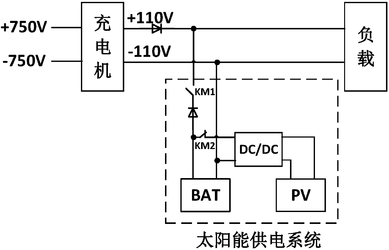
[0021] figure 1 It shows the internal structure of the solar power supply system and the external wiring diagram of the low-voltage electrical system of the vehicle. Under normal working conditions, the DC750V DC bus provides DC110V bus voltage through the charger to supply power to the DC load. In addition, the solar panel PV is converted by a boost converter to provide DC110V, connected to a small energy storage battery box, and both are hung on the DC110V DC bus. In the event of a charger failure, the small energy storage battery box supplies power to the 110V DC load to ensure the normal operation of the load equipment. When the small energy storage battery box is out of power, the solar panel PV is transformed by a boost converter to provide DC110V, which is connected to the small energy storage battery box to charge it. The battery box is behind the diode of the c...


PUM


Abstract

The invention belongs to the technical fields of new energy power generation and energy storage and particularly relates to a vehicle-mounted solar energy power supply system for urban rail vehicles.The vehicle-mounted solar energy power supply system comprises a flexible photovoltaic module, a boost convertor and an energy storage battery box which are sequentially connected and are paved on thetop or side surface of an urban rail vehicle, wherein the energy storage battery box is taken as an auxiliary power supply system of the vehicle and is connected with an external power supply bus ofthe vehicle through a contactor; the flexible photovoltaic module is a photovoltaic film battery, five series-wound photovoltaic film batteries are paved outside each compartment, the maximum power ofeach photovoltaic film battery is 100W, the rated voltage of each photovoltaic film battery is 17.8V, and a series-wound unit with a rated voltage of 89V and the maximum power of 500W is formed through the series connection of the photovoltaic film batteries; and the series-wound units of two compartments are connected in parallel and are connected to the boost convertor with rated power of 1kW,the voltage is converted into 110V, and the series-wound units are incorporated into the energy storage battery box with a rated voltage of 110V, and power is supplied to a 110V bus by the energy storage battery box through a diode.

Description

technical field [0001] The invention belongs to the technical field of new energy power generation and energy storage, and in particular relates to a vehicle-mounted solar power supply system for urban rail vehicles. Background technique [0002] With the country's vigorous promotion of energy conservation and emission reduction, photovoltaics, as a clean energy, are gradually being recognized and promoted, and the government has also introduced a series of measures to support the development of the photovoltaic industry. Compared with other energy sources, photovoltaic technology has many advantages: it does not have any mechanical moving parts; it does not need any fuel except sunlight; it is inexhaustible and so on. The state requires vigorous development of new energy, high-efficiency, and high-safety system technologies and equipment, and the development of rail transit safety, intelligence, and green technologies. Applying photovoltaic technology to the field of urban...

Claims


Application Information

Patent Timeline
Patent Type & Authority Applications(China)
IPC IPC(8): B60L8/00H02J7/35
CPCB60L8/003B60L2200/26H02J7/35Y02B10/10Y02T10/7072
Inventor 齐玉文于青松翟国锐姜久春王子超于昊明王占国
Owner BEIJING JIAOTONG UNIV
Why Eureka
Try Eureka