Barrel-shaped material clamping device achieving grinding and scrap removal
A barrel-shaped object and clamping technology, applied in the direction of grinding/polishing safety devices, machine tools designed for grinding the rotating surface of workpieces, grinding machines, etc., can solve the problems that debris cannot be removed in time, uneven grinding, etc., and achieve grinding Uniform, even sanding effect
- Summary
- Abstract
- Description
- Claims
- Application Information
AI Technical Summary
Problems solved by technology
Method used
Image
Examples
Embodiment 1
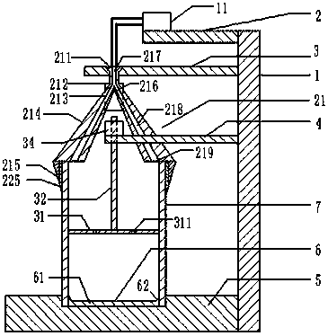
[0035] Such as figure 1 As shown, the clamping barrel device for grinding and removing debris includes a frame 1, on which a first support plate 2, a second support plate 3, a third support plate 4 and a bottom plate 5 are sequentially arranged from top to bottom , the first support plate 2 is provided with a fan 11, the second support plate 3 is provided with a clamp 21, the third support plate 4 is provided with a grinding part, the second support plate 3 and the third support plate 4 are all connected with the machine The frame 1 is detachably connected, and the bottom plate 5 is fixedly connected with the frame 1;
[0036] The clamping part 21 includes a connecting column 211, a matching part 212 and a movable foot 214. The connecting column 211 is connected with the second support plate 3 by mortise and tenon, and the matching part 212 is welded to the connecting column 211. Draw-in slot 213, the draw-in slot 213 is evenly distributed along the boundary of the mating par...
Embodiment 2
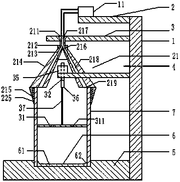
[0040] Such as figure 2 As shown, different from Embodiment 1, the power equipment in this program is a rotary motor 35, the lower end of the central shaft 32 is radially fixed with a cylinder 36, the cylinder 36 is coaxial with the central shaft 32, and the grinding wheel 31 and the cylinder 36 The piston rod 37 is connected; the rotating motor 35 controls the rotation of the central shaft 32. Since the central shaft 32 is radially fixed to the cylinder axis, the rotation of the central shaft 32 drives the rotation of the cylinder 36. Because the piston rod 37 is inside the cylinder 36, the rotation of the cylinder 36 The rotation of the piston rod 37 is driven. Since the piston rod 37 is fixedly connected with the emery wheel 31, the emery wheel 31 also rotates around the center of the emery wheel 31, and the outer circumference of the emery wheel 31 fits with the inner wall of the barrel 7. Therefore, the emery wheel 31 The effect of rotation is to polish the inner wall of...
Embodiment 3
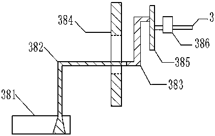
[0043] Such as image 3 and Figure 4 As shown, the difference from Embodiment 1 is that the power equipment in this solution includes a rotating motor 35, a fixed plate 381, a fixed shaft 382, a connecting shaft 383, a limit slide 384, an eccentric wheel 385 and an auxiliary motor 386; the central shaft 32 is connected with the rotary motor 35, the rotary motor 35 is fixed on the fixed plate 381, the fixed plate 381 is fixedly connected with the fixed shaft 382, the fixed shaft 382 passes through the cavity of the limit slide 384 and is fixedly connected with the connecting shaft 383, the limit slide The road 384 is fixed on the frame 1, and the coupling shaft 383 is connected to any eccentric position of the eccentric wheel 385. The eccentric wheel 385 is controlled by the auxiliary motor 386 to rotate. Three support plates 4.
[0044] Eccentric wheel 385, connecting shaft 383, auxiliary motor 386, limit slideway 384 constitute a crank connecting rod structure, auxilia...
PUM
 Abstract
Description
Claims
Application Information
 - R&D
- Intellectual Property
- Life Sciences
- Materials
- Tech Scout
- Unparalleled Data Quality
- Higher Quality Content
- 60% Fewer Hallucinations
Browse by: Latest US Patents, China's latest patents, Technical Efficacy Thesaurus, Application Domain, Technology Topic, Popular Technical Reports.
© 2025 PatSnap. All rights reserved.Legal|Privacy policy|Modern Slavery Act Transparency Statement|Sitemap|About US| Contact US: help@patsnap.com


