an interferometer

An interferometer and light technology, which is applied in the field of interferometers, can solve the problems of large optical path fluctuation and deviation, and achieve the effect of improving accuracy and satisfying ultrafast two-dimensional electron spectroscopy experiments.

Active Publication Date: 2019-04-23
NANJING UNIV
View PDF17 Cites 0 Cited by
  • Summary
  • Abstract
  • Description
  • Claims
  • Application Information

AI Technical Summary

Problems solved by technology

Phase locking means that the time delay between two pulses, that is, the accuracy of the optical path difference must be controlled at the order of 1 / 100 wavelength. Generally, in the free optical path built in the laboratory, the fluctuation of the optical path is large, and often On the order of hundreds of nanometers, it cannot meet the needs of ultrafast two-dimensional electron spectroscopy experiments, so additional methods and means are needed to achieve phase locking

Method used


Image

  • an interferometer
  • an interferometer
  • an interferometer

Examples


Embodiment Construction

[0041] The present invention will be further described in detail below with reference to the drawings and embodiments. It can be understood that the specific embodiments described here are only used to explain the present invention, but not to limit the present invention. In addition, it should be noted that, for ease of description, the drawings only show a part but not all of the structure related to the present invention.

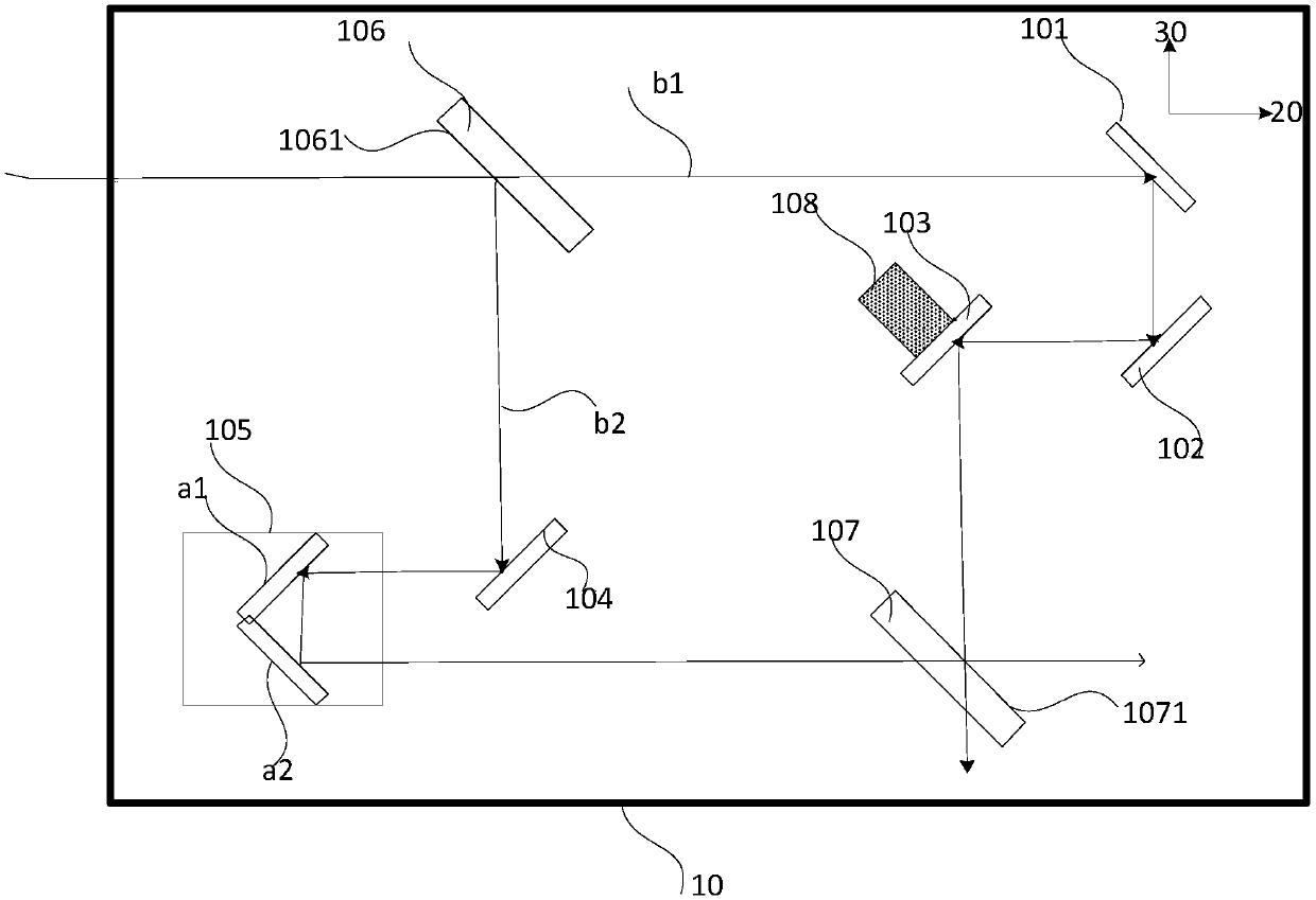
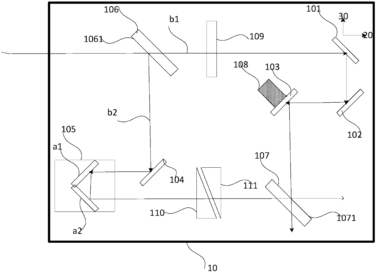
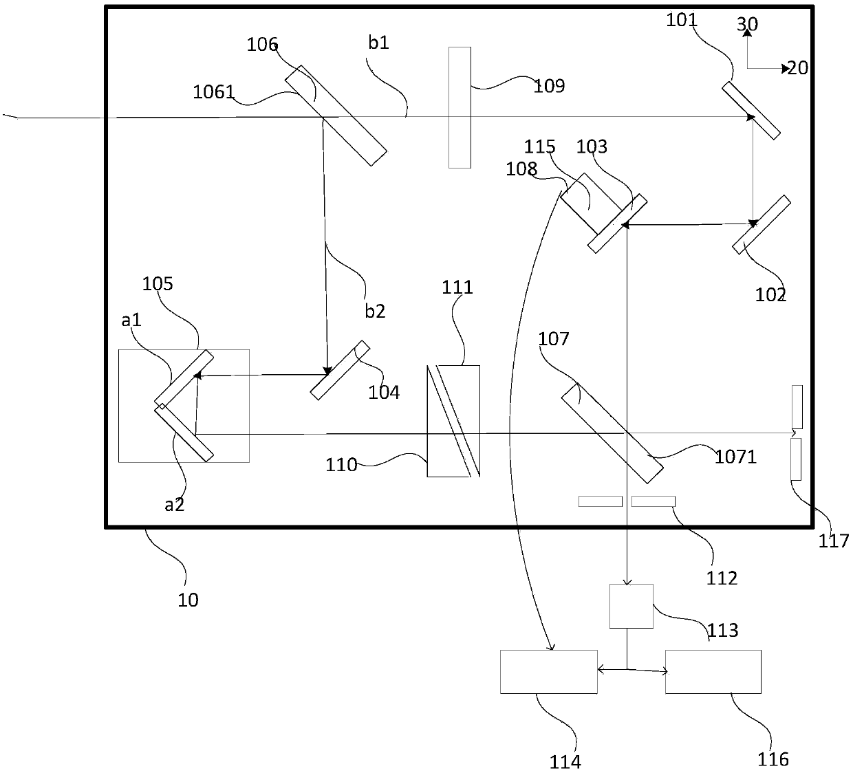
[0042] figure 1 It is a schematic diagram of an interferometer device provided by an embodiment of the present invention. An interferometer provided by an embodiment of the present invention includes: a base 10;

[0043] The light propagation part formed on the base 10 includes a first light propagation path b1 and a second light propagation path b2; along the first light propagation path b1, a second reflector 101, a third reflector 102, and A fourth reflector 103; along the second light propagation path b2, a first reflector 104 and an optical delay line ...


PUM


Abstract

The invention discloses an interferometer. The interferometer comprises a base, a light propagation portion which is formed on the base and comprises a first light propagation path and a second lightpropagation path, a phase locking module which is formed on the base, is connected with a fourth reflector of the first light propagation path and is used for adjusting the position of the fourth reflector to make phase difference of a first sub light beam and a second sub light beam not greater than 0.06 rad and make light path difference of the first light propagation path and the second light propagation path not greater than 6nm. Compared with an interferometer in the prior art, the interferometer is advantaged in that the active phase locking purpose can be realized, ultrafast two-dimensional electronic spectrum experiment demands can be satisfied, and accuracy of the experiment result can be improved.

Description

Technical field [0001] The embodiment of the present invention relates to the field of optical technology, in particular to an interferometer. Background technique [0002] With the rapid development of ultra-fast laser technology, the ultra-fast time-resolved pump-detection technology that uses two ultra-short pulse lasers with a certain time delay to interact with the sample can obtain the sample in nanosecond, pico Transient dynamics in the time scale of seconds or even femtoseconds. For various condensed phase systems that are more complex and extremely common, the more powerful ultrafast two-dimensional Fourier transform electronic spectroscopy technology developed in recent years can better reflect the electronic dynamics of the material system. Quantum coherence effect. [0003] The ultrafast two-dimensional electron spectroscopy experiment detects the weak third-order nonlinear optical response of the sample after three pulsed lasers A, B, and C with a certain controllabl...

Claims


Application Information

Patent Timeline
Patent Type & Authority Patents(China)
IPC IPC(8): G02B17/06
CPCG02B17/0668
Inventor 朱伟达王睿张春峰王国栋肖敏
Owner NANJING UNIV
Why Eureka
Try Eureka