Disintegration tank with shock resistance

A shock-resistant and high-capacity technology, applied in the field of decay pools, can solve problems such as poor anti-accident shock capability, high cost, and complex control and operation management in the later stage, so as to achieve the effect of anti-accident shock capability and improve safety redundancy

Active Publication Date: 2018-04-13
GUANGZHOU URBAN PLANNING & DESIGN SURVEY RES INST
View PDF4 Cites 3 Cited by
  • Summary
  • Abstract
  • Description
  • Claims
  • Application Information

AI Technical Summary

Problems solved by technology

Disadvantages of the intermittent decay pool are: in order to ensure the reliability of the effluent, a large amount of radioactive waste water must be stored, and the total volume of the design pool shall not be less than the total discharge of radioactive waste water with 20 half-lives of the longest half-life isotope; multiple grids are set, and each grid is matched Solenoid valves and submersible pumps make the whole pool occupy a large area, high cost, and relatively complicated control and operation management in the later stage, so it is not suitable for places with tight land use
The disadvantage of the continuous decay pool is that it only stores radioactive wastewater with the minimum decay time specified in the specification, and its ability to resist accident impact is poor; if accidents such as radioactive material leakage occur, and the radioactive material in the wastewater increases, the wastewater has not yet decayed in the decay pool. When it reaches the allowable discharge concentration, it has to be discharged, which will cause radioactive pollution accidents

Method used


Image

  • Disintegration tank with shock resistance
  • Disintegration tank with shock resistance

Examples


Embodiment Construction

[0018] The specific implementation manners of the present invention will be further described in detail below in conjunction with the accompanying drawings and embodiments. The following examples are used to illustrate the present invention, but are not intended to limit the scope of the present invention.

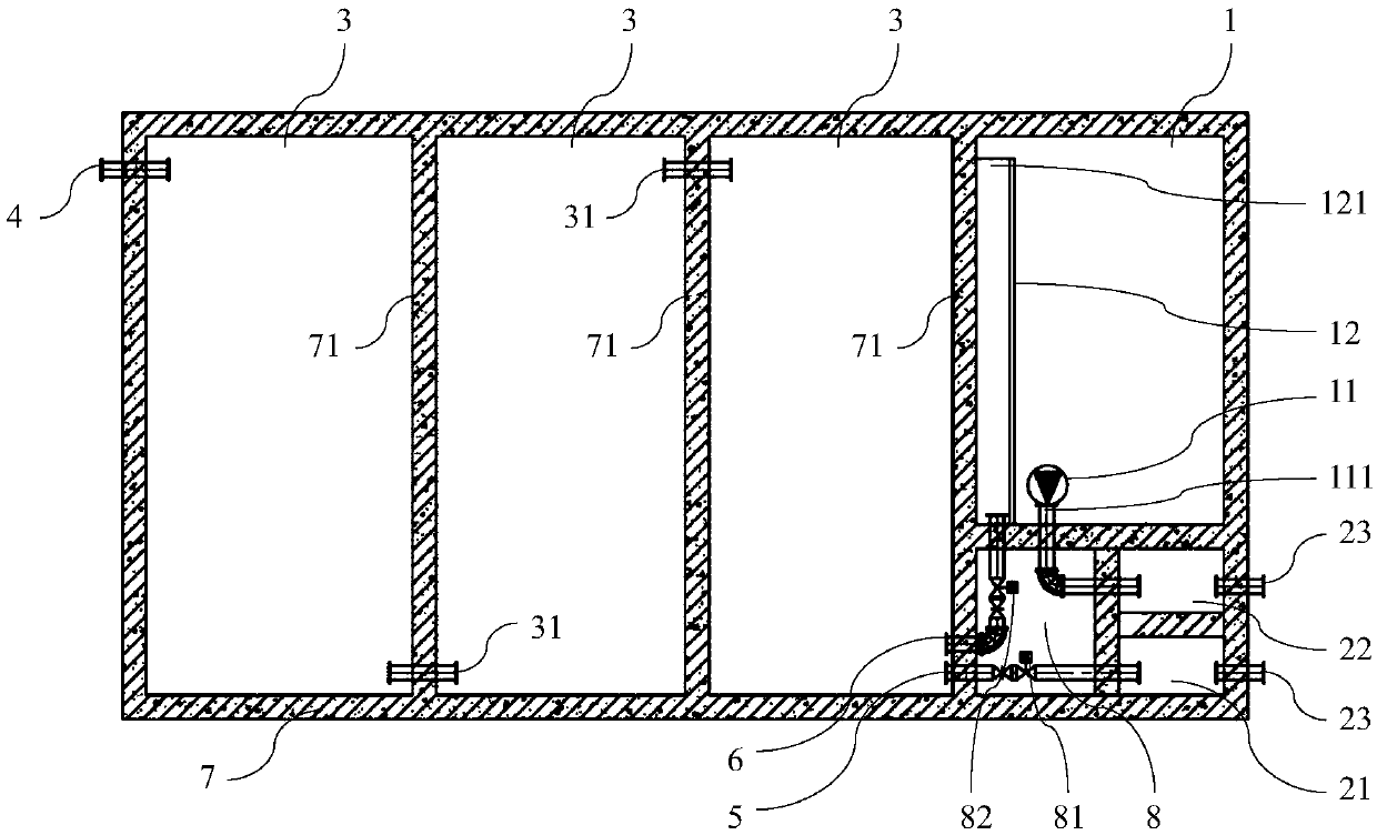
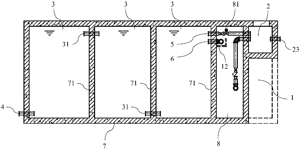
[0019] to combine figure 1 with figure 2 As shown, the decay cell with impact resistance of the present invention is schematically shown, including an adjustment cell 1, a detection cell 2 and a plurality of decay cells 3 connected in sequence through conduits 31, and the detection cell 2 includes a first detection cell 21 and The second detection pool 22, the decay pool 3 located at the head end is connected to be provided with the water inlet pipe 4, and the decay pool 3 located at the tail end is communicated with the first detection pool 21 and the regulating pool 1 through the water outlet pipe 5 and the bypass pipe 6 respectively, and the water outlet pipe 5 and t...


PUM


Abstract

The invention relates to the field of wastewater treatment and in particular relates to a disintegration tank with shock resistance. The disintegration tank comprises a regulating tank, a detecting tank and a plurality of disintegration tank bodies sequentially communicating by guide pipes; the detecting tank comprises a first detecting tank and a second detecting tank; the disintegration tank body located at the head end is provided with a water inlet pipe in a communicating way; the disintegration tank body located at the tail end separately communicates with the first detecting tank and theregulating tank by a water outlet pipe and a bypass pipe; the water outlet pipe is provided with a first control valve, and the bypass pipe is provided with a second control valve; the regulating tank communicates with the second detecting tank; and a drainage outlet communicating with the outside is formed in each of the first detecting tank and the second detecting tank. The disintegration tankwith shock resistance is additionally provided with the regulating tank on the basis of a traditional continuous disintegration tank, and the regulating tank is capable of temporarily storing wastewater, so that the phenomenon that wastewater not reaching a discharge standard in the disintegration tank has to be discharged when radioactive substances are leaked to result in radioactive contamination accidents is avoided.

Description

technical field [0001] The invention relates to the field of sewage treatment, in particular to a decay pool with impact resistance. Background technique [0002] Since the 1950s, my country has begun to use radioisotopes for medical diagnosis and treatment of diseases. The excreta produced by patients taking and injecting radioisotopes during the diagnosis and treatment of radioisotopes, the isotope-packing containers, cups, laboratory cleaning water, and radioactive waste water discharged from labeled compounds must be properly treated so that Wastewater can be discharged into urban municipal sewage pipes only when the radioactivity of the waste water is reduced to below the safe value stipulated by the state. Radioactive isotopes used in hospitals for diagnosis and treatment are characterized by short half-lives of nuclides and low toxicity. One of the common methods for treating medical radioisotope wastewater is the storage decay method. [0003] According to the "Ho...

Claims


Application Information

Patent Timeline
Patent Type & Authority Applications(China)
IPC IPC(8): G21F9/22G21F9/06
CPCG21F9/06G21F9/22
Inventor 蔡昌明曹秋霞刘碧娟刘东燕汤建玲张君彦王思臻
Owner GUANGZHOU URBAN PLANNING & DESIGN SURVEY RES INST
Why Eureka
Try Eureka