Substation grounding grid in frozen earth area and design method thereof

A technology of substation grounding grid and design method, applied in the directions of circuits, connections, electrical components, etc., can solve the problems of increasing the construction cost of grounding grids, environmental pollution, etc., and achieve the effects of reducing investment, expanding land acquisition area, and optimizing the structure of grounding grids

Active Publication Date: 2018-04-13
POWERCHINA HEBEI ELECTRIC POWER SURVEY & DESIGN INST CO LTD
View PDF5 Cites 7 Cited by
  • Summary
  • Abstract
  • Description
  • Claims
  • Application Information

AI Technical Summary

Problems solved by technology

These laying methods have certain applicability, but in areas with deep seasonal frozen soil, a large amount of construction work will be added
And when the substation grounding grid laid in the above way cannot meet the requirements of grounding resistance, step voltage and contact potential, additional resistance reduction measures are required, usually including: adopting deep well grounding electrodes, adding chemical resistance reducing agents to the soil, replacing Soil, sewage introduction, external introduction of horizontal grounding electrodes, etc. These resistance reduction measures will bring about the increase of the construction cost of the grounding grid and environmental pollution.

Method used


Image

  • Substation grounding grid in frozen earth area and design method thereof
  • Substation grounding grid in frozen earth area and design method thereof
  • Substation grounding grid in frozen earth area and design method thereof

Examples


Embodiment Construction

[0029] Below in conjunction with accompanying drawing and specific embodiment the present invention is described in further detail:

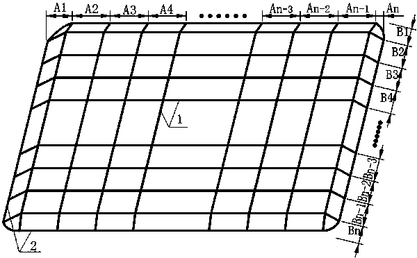
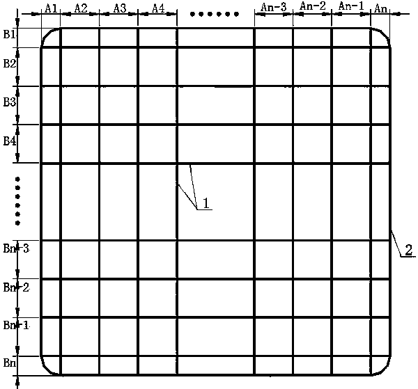
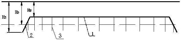
[0030] The invention discloses a grounding grid of a substation in a permafrost area and a design method thereof, and specifically describes the structure of the grounding grid and how to design specific parameters of the structure of the grounding grid. The scheme is applied to the construction of a substation and is applicable to various The design and construction of substation grounding grids with voltage levels are especially suitable for the design and construction of substation grounding grids in deep seasonal frozen soil regions.

[0031] The substation grounding grid in the present invention includes several horizontal main lines and several vertical main lines, and the horizontal main lines and the vertical main lines are connected to form a network structure as a grounding body, and the horizontal main lines and the vertical main lines...


PUM


Abstract

The invention relates to a substation grounding grid in frozen earth area and a design method thereof and belongs to the technical field of substation construction. The grounding grid is a mesh structure in which a plurality of horizontal trunk lines and longitudinal trunk lines are connected, and the grounding grid includes a horizontal grounding grid and a sinking grounding grid where the edge of the horizontal grounding grid is bent downwards. The horizontal grounding grid is located in a frozen earth layer. The lowermost end of the sinking grounding grid is located below the frozen earth layer; and the intersections of the horizontal trunk lines and the longitudinal trunk lines are connected with grounding resistors in the downward directions, and the lowermost ends of the grounding resistors extend below the frozen earth layer. The invention optimizes the structure of the grounding grid, and reduces the stepping voltage and the contact potential of the grounding grid, thereby meeting the safety performance requirements of the grounding grid in areas with high soil resistivity and deep seasonal frozen earth. The invention does not need to increase the amount of material of thegrounding grid, does not need to expand the land acquisition area of the grounding grid and does not use additional chemical resistance-reducing substances, and reduces the investment of the project.

Description

technical field [0001] The invention relates to a substation grounding grid in a permafrost region and a design method thereof, belonging to the technical field of substation construction. Background technique [0002] The substation grounding grid must meet the requirements of grounding resistance, safe step voltage and contact potential to meet the personal safety of workers in the substation and the safe operation of various electrical equipment. The surface permafrost formed in the freezing season in seasonally frozen regions has a serious impact on the safety performance of the ground network. The grounding resistance, contact potential and step voltage of the grounding system vary with the thickness and resistivity of the permafrost layer. When the thickness of the frozen soil layer is less than the laying depth of the ground grid, the safety performance of the ground grid is less affected; and when the thickness of the frozen soil layer exceeds the buried depth of th...

Claims


Application Information

Patent Timeline
Patent Type & Authority Applications(China)
IPC IPC(8): H01R4/66H01R43/00
CPCH01R4/66H01R43/00
Inventor 刘森刘情新孙凯航温世运赵东成屈彦明
Owner POWERCHINA HEBEI ELECTRIC POWER SURVEY & DESIGN INST CO LTD
Why Eureka
Try Eureka