
Optical fiber microphone probe and optical fiber microphone system

A technology of microphone and optical fiber, which is applied in the field of fiber optic microphone probe and fiber optic microphone system, can solve the problems of narrowing frequency response range, low sensitivity, and inability to achieve high sensitivity and wide frequency response at the same time, and achieve high sensitivity and wide frequency sound, expand the frequency response range, and increase the effect of the elastic coefficient

Active Publication Date: 2018-04-13
THE THIRD RES INST OF CHINA ELECTRONICS TECH GRP CORP
View PDF7 Cites 7 Cited by
  • Summary
  • Abstract
  • Description
  • Claims
  • Application Information

AI Technical Summary

Problems solved by technology

The larger the diaphragm size, the higher the sensitivity and narrow the frequency response range; the smaller the diaphragm size, the wider the frequency response range and reduce the sensitivity
Therefore, it is difficult for traditional electrical microphones to achieve high sensitivity and wide frequency response at the same time
If the metal film is directly used to develop the fiber optic microphone probe, on the one hand, there is a problem that high sensitivity and wide frequency response cannot be achieved at the same time; Corrosion and other effects; if a non-metallic diaphragm without a corrugated structure is used, there is also the problem that high sensitivity and wide frequency response cannot be achieved at the same time
[0004] Most of the existing fiber optic microphones use planar diaphragms without corrugated structures, and the materials of the planar diaphragms are mostly metal, silicon and polymers, etc., which makes it difficult for the existing fiber optic microphones to achieve the optimum state of sensitivity and frequency response range at the same time

Method used


Image

  • Optical fiber microphone probe and optical fiber microphone system
  • Optical fiber microphone probe and optical fiber microphone system
  • Optical fiber microphone probe and optical fiber microphone system

Examples


Embodiment Construction

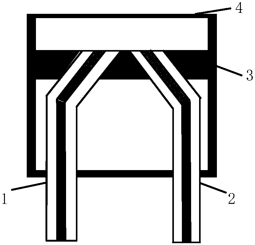
[0021] figure 1 A schematic plan view of the first fiber optic microphone probe provided by an embodiment of the present invention.

[0022] In one example, as in figure 1 As shown, the fiber optic microphone probe is an intensity type fiber optic microphone probe, including: diaphragm 4, optical fiber 1, optical fiber 2, housing 3 and reflective film 12 (not shown in the figure), wherein, 4 diaphragms are arranged inside the housing 3 , the reflective film 12 is arranged on the diaphragm, one end of the optical fiber 1 and the optical fiber 2 is arranged inside the casing 3, and has a certain distance from the diaphragm 4, and the other end of the optical fiber 1 and the optical fiber 2 is arranged outside the casing 3, Diaphragm 4 is made of SiO 2 composition and has a corrugated structure.

[0023] In one example, the diaphragm 4 is square, and may also be in other shapes.

[0024] In one example, the reflective film 12 is disposed at the center of the diaphragm 4 , and...


PUM


Abstract

The embodiment of the invention provides an optical fiber microphone probe and an optical fiber microphone system. A diaphragm made of a composition containing SiO2 is adopted, and the diaphragm adopts a corrugated structure, the stress of the diaphragm is released, the elastic coefficient of the diaphragm is increased, the sensitivity is improved and the frequency response range is expanded underthe premise that the resonant frequency is not reduced, and the problem that an existing optical fiber microphone probe cannot simultaneously achieve higher sensitivity and wider frequency responsescan be solved.

Description

technical field [0001] The invention relates to the field of acoustic technology, in particular to an optical fiber microphone probe and an optical fiber microphone system. Background technique [0002] As a new type of microphone, the fiber optic microphone has the advantages of high sensitivity, strong anti-electromagnetic interference, low transmission loss, and long transmission distance. The higher sensitivity can improve the working distance of the acoustic signal detection and recognition system; the anti-electromagnetic interference ability makes it suitable for use in special environments such as strong radiation, high temperature and high humidity, and can be applied to long-distance target detection in complex terrain environments. Transformer detection, gas pipeline monitoring, border early warning monitoring and other fields have great application potential. [0003] The diaphragm used in traditional electrical microphone probes is mostly a flat metal diaphragm...

Claims


Application Information

Patent Timeline
Patent Type & Authority Applications(China)
IPC IPC(8): H04R23/00
CPCH04R23/008
Inventor 周瑜王坤博魏晓村刘超马宁
Owner THE THIRD RES INST OF CHINA ELECTRONICS TECH GRP CORP
Learn More