
330kV double-loop four-column steel pipe pole terminal tower in high-altitude area

A double-circuit, high-altitude technology, applied to towers, building types, buildings, etc., can solve problems such as poor economic benefits, difficulty, and large footprint of iron tower foundations, so as to improve the bearing capacity of nodes and reduce the side width , the effect of reducing the floor area

Pending Publication Date: 2018-04-17
NORTHWEST ELECTRIC POWER DESIGN INST OF CHINA POWER ENG CONSULTING GROUP +1
View PDF9 Cites 2 Cited by
  • Summary
  • Abstract
  • Description
  • Claims
  • Application Information

AI Technical Summary

Problems solved by technology

At present, my country's high-altitude 330kV double-circuit terminal towers mostly use conventional dry-shaped lattice-type angle steel towers. This type of iron tower base occupies a large area and has an unsightly shape. Modification and adjustment of the line path will lead to an increase in the cost of the line body and relatively poor economic benefits
At the same time, due to the limitation of follow-up, the load-bearing characteristics of traditional steel pipe poles are limited, and it is difficult to be used in high-voltage transmission lines. For terminal towers, the unbalanced load is much greater than that of straight-line towers and small-angle tension towers. Traditional It is more difficult to meet the load-bearing requirements of high-voltage terminal towers with the steel pipe pole structure design and node design
On the other hand, limited by the low temperature environment and personnel hypoxia in high-altitude areas, a large number of welding processes for traditional lattice multi-column steel pipe poles are not suitable for high-altitude areas

Method used


Image

  • 330kV double-loop four-column steel pipe pole terminal tower in high-altitude area
  • 330kV double-loop four-column steel pipe pole terminal tower in high-altitude area
  • 330kV double-loop four-column steel pipe pole terminal tower in high-altitude area

Examples


Embodiment Construction

[0027] The technical solutions in the embodiments of the present invention will be clearly and completely described below in conjunction with the accompanying drawings in the embodiments of the present invention. The embodiments described herein are only some of the embodiments of the present invention, not all of them. Based on the embodiments of the present invention, all other embodiments obtained by persons of ordinary skill in the art without creative efforts fall within the protection scope of the present invention.

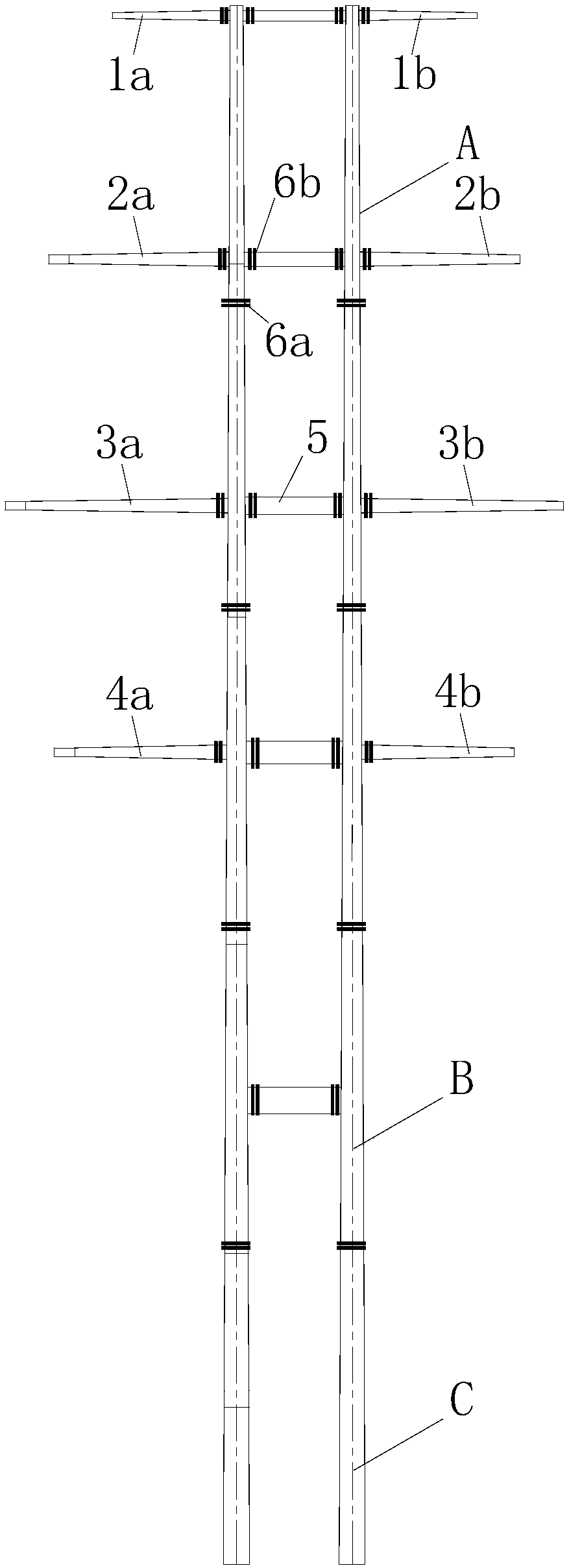
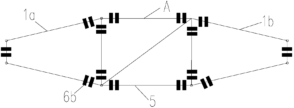
[0028] Such as figure 1 and figure 2 As shown, the 330kV double-circuit four-column steel pipe pole terminal tower in the high altitude area of ​​the present invention is composed of a tower head A, a tower body B and a tower leg C, all of which are composed of steel pipe members of different pipe diameters spliced ​​by bolts. The tower head A includes four layers of cross arms, the top layer is the ground wire cross arm, including the left ground wire ra...


PUM


Abstract

The invention discloses a 330kV double-loop four-column steel pipe pole terminal tower in a high-altitude area. A treatment mode that the width of a tower body opening is identical to the spacing of tower leg roots is adopted, the occupation area of an iron tower is reduced, and about 60% of land expropriation cost is reduced under comparison of an angle steel tower with same conditions; meanwhile, a rectangular cross section is adopted, the lateral rigidity is improved to resist the load due to the lateral tension of the terminal tower in the horizontal direction of the iron tower, the widthof the side surface is properly reduced on the premise that the vertical rigidity recruitment is met, the unnecessary horizontal separation surface is reduced, and according to the measure, about 10%of the tower weight is reduced under comparison of a same-type steel pipe pole with a square cross section; a mode that the cross section of a main rod is continuously and gradually increased from thetop to the bottom is adopted, a traditional mode that all segments of steel pipes with equal diameters are connected is not adopted, and the influence of rigidity sudden change and difficult construction treatment due to cross section change of all segments of connection portions is reduced.

Description

technical field [0001] The invention relates to the field of power transmission line engineering towers, in particular to a 330kV double-circuit four-column steel pipe pole terminal tower in a high-altitude area. Background technique [0002] In the construction of transmission line projects, there are often complex situations such as limited line corridor width, limited tower base shape, and coordination between tower requirements and scenic landscapes. Line paths, tower location selection, and tower appearance are often subject to more restrictions. At present, my country's high-altitude 330kV double-circuit terminal towers mostly use conventional dry-shaped lattice-type angle steel towers. This type of iron tower base occupies a large area and has an unsightly shape. Modifying and adjusting the line path will lead to an increase in the cost of the line body and relatively poor economic benefits. At the same time, due to the limitation of follow-up, the load-bearing charac...

Claims


Application Information

Patent Timeline
Patent Type & Authority Applications(China)
IPC IPC(8): E04H12/08E04H12/24
CPCE04H12/08E04H12/24
Inventor 魏鹏袁俊查玮沈巍巍白左霞刘飞陈雪安娟张祥成
Owner NORTHWEST ELECTRIC POWER DESIGN INST OF CHINA POWER ENG CONSULTING GROUP
Learn More