Wide input range interleaved parallel high-efficiency step-up DC converter for fuel cells

A DC converter and fuel cell technology, which is applied in the direction of converting DC power input to DC power output, adjusting electrical variables, and converting devices for output power, etc., can solve the problem of high voltage gain, large voltage stress, increased switching loss and electromagnetic interference and other problems, to achieve the effect of wide voltage gain and small input current ripple

Inactive Publication Date: 2020-04-10
TIANJIN UNIV
View PDF3 Cites 0 Cited by
  • Summary
  • Abstract
  • Description
  • Claims
  • Application Information

AI Technical Summary

Problems solved by technology

[0004] Traditional isolated step-up DC converters are easy to achieve high voltage gain, but due to the leakage inductance of the transformer, it will generate a large voltage stress, which increases switching loss and electromagnetic interference

Method used


Image

  • Wide input range interleaved parallel high-efficiency step-up DC converter for fuel cells
  • Wide input range interleaved parallel high-efficiency step-up DC converter for fuel cells
  • Wide input range interleaved parallel high-efficiency step-up DC converter for fuel cells

Examples


Embodiment 1

[0048] 1. Topology

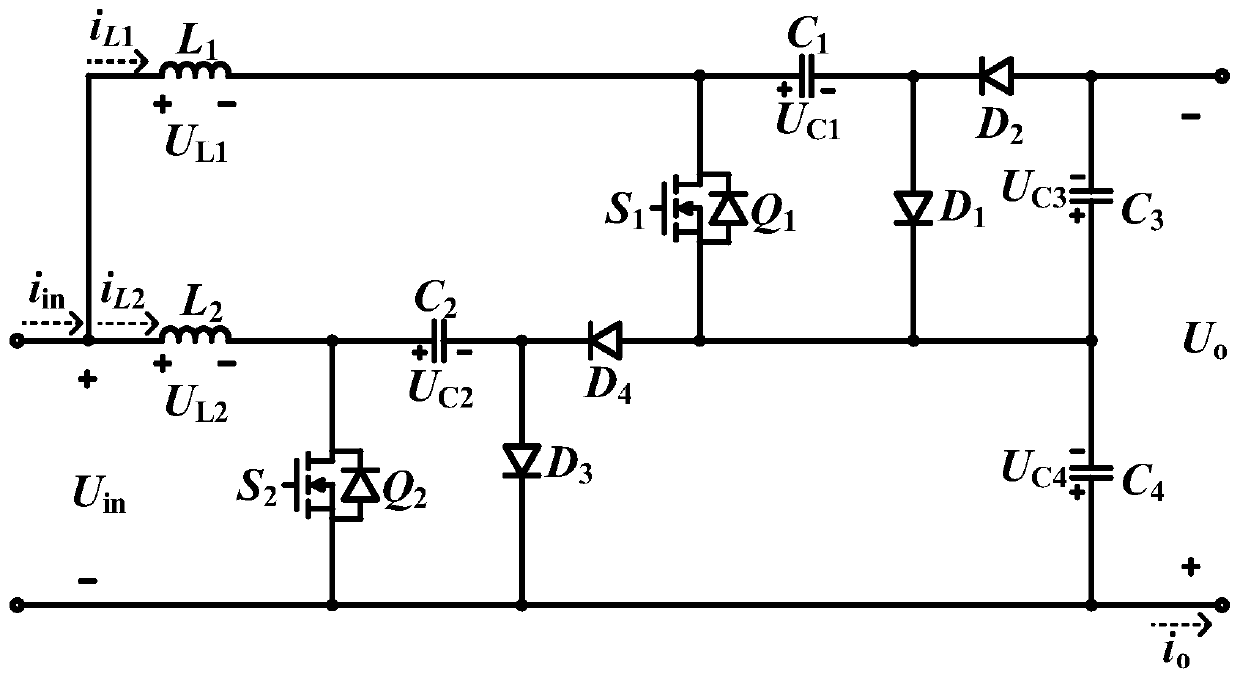
[0049] The invention is improved based on cascaded DC boost converters and interleaved parallel DC boost converters combined with switched capacitor networks. The input end of the DC converter is connected to the fuel cell, that is, the power input end U in Indicates; inductance L 1 and L 2 It is an interleaved parallel structure, which reduces the input current ripple and improves the efficiency of the converter; the capacitor C 3 and C 4 Parallel output improves the gain of the converter and reduces the voltage stress of the power device; the output end is connected to the high-voltage DC bus.

[0050] 2. Wide voltage gain

[0051] d 1 and d 2 Respectively power switch Q 1 and Q 2 The duty cycle and d 1 = d 2 = d, Q 1 and Q 2 The drive signals differ by 180°. According to the power switch Q 1 and Q 2 On-off situation, the topology proposed by the present invention has 4 switch states "S 1 S 2 "={00,01,10,11}, where "1" means power switc...

Embodiment 2

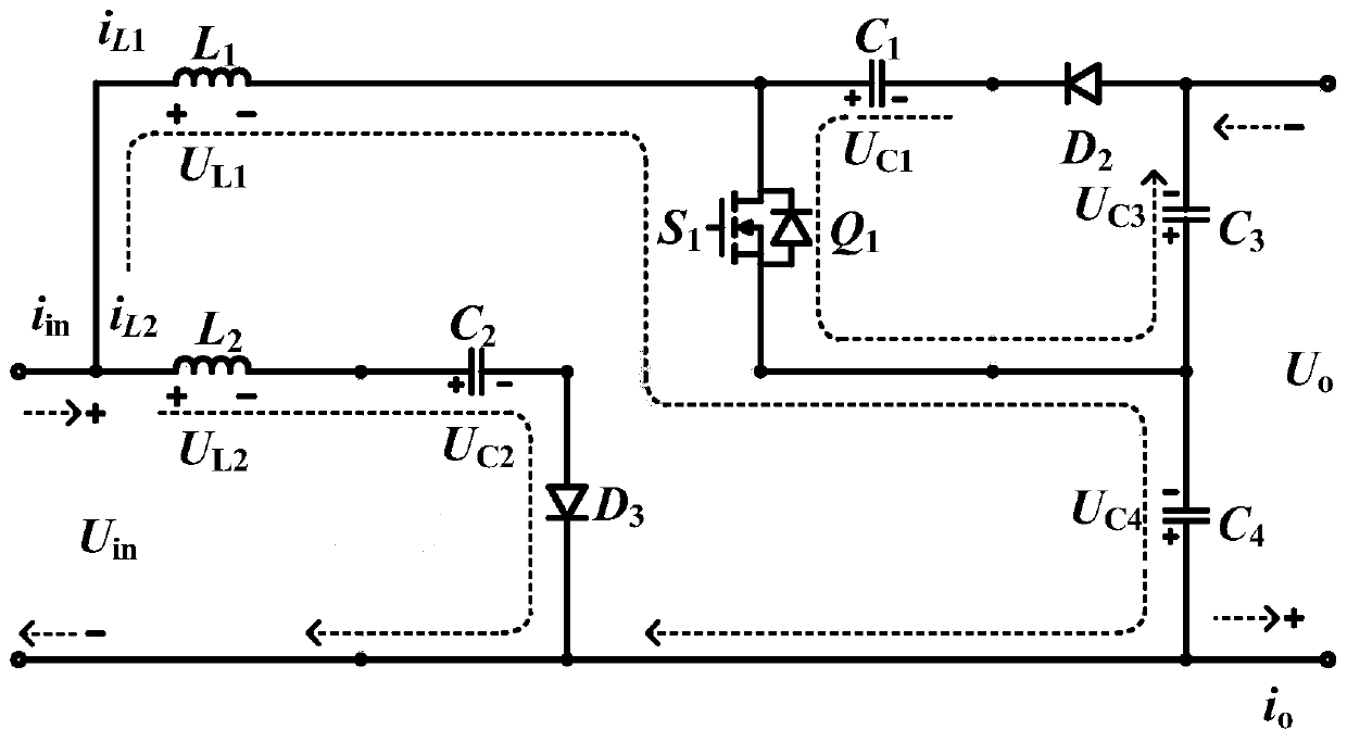
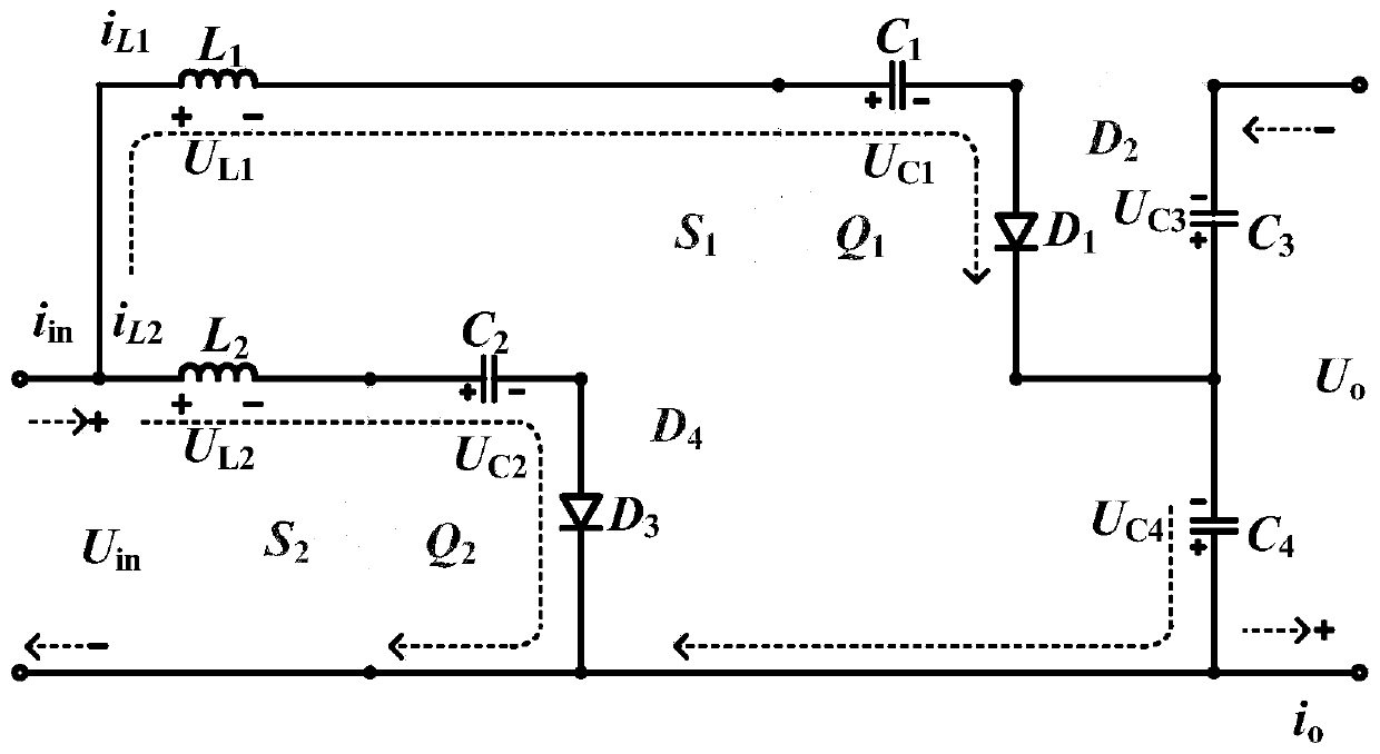
[0082] Below to figure 1 The wide input range interleaved parallel high-efficiency boost DC converter topology shown, figure 2 , 3 , topological equivalent circuit diagrams of 4 and 5 and Image 6 with 7 The important working waveforms when the new topology is running stably, and the principle of the solution in the first embodiment will be described. When 01 S 2 = 00, 01, 10 three switching states; and when 0.5≤d1 S 2 =11,01,10 three switch states. The following are respectively for "S 1 S 2 "={00,01,10,11}4 switch states are explained.

[0083] Switching state 10: Power switch Q 1 Open Q 2 off, the diode D 1 and D 4 off, D 2 and D 3 conduction, then the equivalent circuit such as figure 2 shown. u in and capacitance C 4 for L 1 charging, the inductor current i L1 increases linearly, the inductor current i L2 Decreases linearly. Inductor current i L2 For capacitance C 2 is charged, the capacitor C 1 To charge C 3 Electricity, C 2 and C 3 The volt...


PUM


Abstract

The invention, which relates to the technical field of the power electronic power conversion, provides a wide-input-range interleaved parallel type high-efficiency boost direct-current converter for afuel cell so that the input current ripple can be reduced, the converter efficiency can be improved, the converter gain can be increased, and the voltage stress of the power device can be reduced. And thus the direct-current converter is more suitable for the occasion of voltage conversion of the fuel cell. The direct-current converter is composed of inductors L1 and L2, capacitors C1, C2, C3 andC4, diodes D1, D2, D3, and D4, and power switches Q1 and Q2. The power switch Q1, the capacitors C1 and C3, and the diodes D1 and D2 form a direct-current boost converter A with the reversed-polarityoutput; and the inductor L2, the power switch Q2, the capacitors C2 and C4, and the diodes D3 and D4 form a direct-current boost converter B with the reversed-polarity output. The wide-input-range interleaved parallel type high-efficiency boost direct-current converter is mainly applied to the power electronic power conversion occasion.

Description

technical field [0001] The invention relates to the technical field of power electronic power conversion, in particular to a wide input range interleaved parallel high-efficiency step-up DC converter for fuel cells, which belongs to the application occasion of fuel cell unidirectional step-up DC converters. Specifically, it relates to a wide input range interleaved parallel high-efficiency step-up DC converter for fuel cells. Background technique [0002] With the massive exploitation and utilization of fossil fuels, a series of energy problems and environmental problems have been triggered. The key to solving environmental problems is to fundamentally solve the problem of energy structure and research and develop clean energy technology. The fuel cell is an efficient and clean energy that meets this environmental requirement. A fuel cell directly converts chemical energy into electrical energy isothermally and electrochemically. It does not go through the heat engine pro...

Claims


Application Information

Patent Timeline
Patent Type & Authority Patents(China)
IPC IPC(8): H02M3/155H02M1/15
CPCH02M1/15H02M3/155
Inventor 王萍毕华坤
Owner TIANJIN UNIV
Why Eureka
Try Eureka