
Punching die with polishing function

A technology of stamping dies and functions, which is applied in the field of stamping dies with polishing function, can solve the problems of increased process, lower product pass rate, and uneven product surface, so as to improve the pass rate and save the process and plane of secondary processing good effect

Active Publication Date: 2018-04-20
ZHEJIANG ZHONGTONG AUTO PARTS
View PDF5 Cites 5 Cited by
  • Summary
  • Abstract
  • Description
  • Claims
  • Application Information

AI Technical Summary

Problems solved by technology

[0005] Aiming at the deficiencies of the prior art, the present invention provides a stamping die with a polishing function, which solves the problem that most of the above-mentioned stamping dies in the current market, when stamping a product, due to excessive stamping force, And the problem of mold use time will lead to uneven surface of the product that comes out during mold closing, and a large number of sharp edges due to vigorous stamping at the corners, so that secondary processing or polishing is required, which not only increases the process, but also Product pass rate drops, technical problems that increase a lot of cost

Method used


Image

  • Punching die with polishing function
  • Punching die with polishing function
  • Punching die with polishing function

Examples


Embodiment Construction

[0025] The following will clearly and completely describe the technical solutions in the embodiments of the present invention with reference to the accompanying drawings in the embodiments of the present invention. Obviously, the described embodiments are only some, not all, embodiments of the present invention. Based on the embodiments of the present invention, all other embodiments obtained by persons of ordinary skill in the art without making creative efforts belong to the protection scope of the present invention.

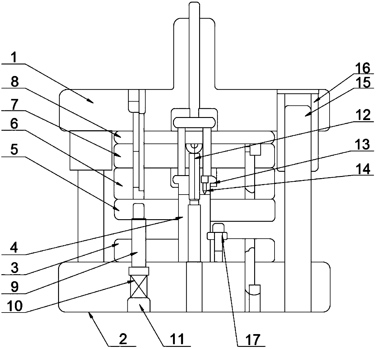
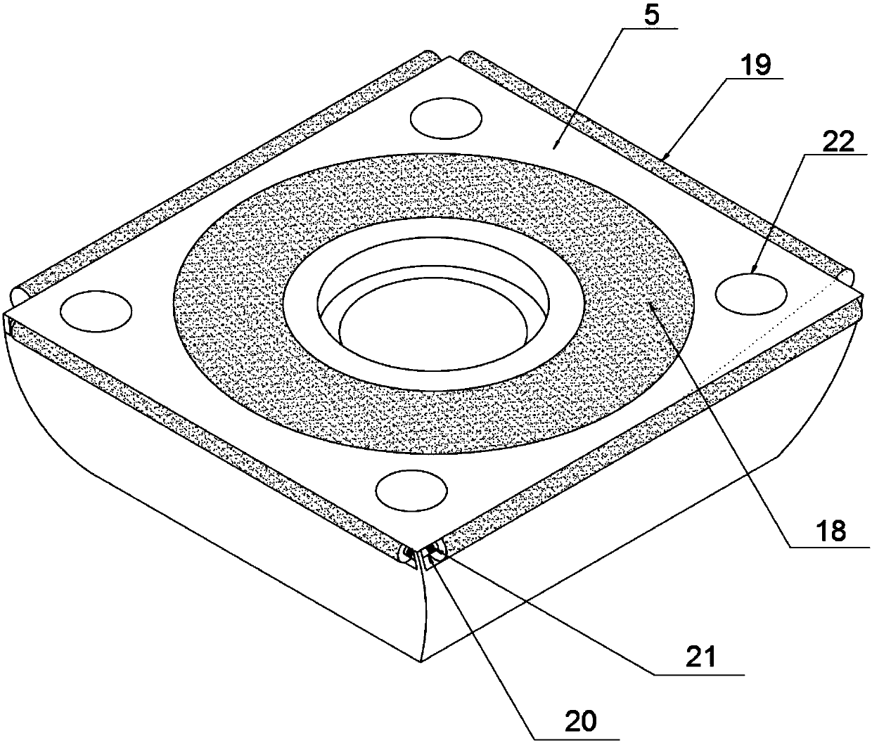
[0026] Embodiments of the present invention provide a stamping die with a polishing function, such as Figure 1-3 As shown, it includes an upper mold base (1) and a lower mold base (2), and is characterized in that: the bottom end of the upper mold base (1) is provided with a backing plate (8), and the bottom end of the backing plate (8) is provided with a concave The mold fixing plate (7), the bottom of the die fixing plate (7) is provided with a concave temp...


PUM


Abstract

The invention provides a punching die with a polishing function, and relates to the field of punching dies. The punching die comprises an upper die base and a lower die base. A cushion plate is arranged at the bottom end of the upper die base. A female die fixing plate is arranged at the bottom end of the cushion plate. A female die plate is arranged at the bottom end of the female die fixing plate. A discharging punching composite male die penetrates the center of an unloading plate and is connected with a jacking type male die. The jacking type male die penetrates the unloading block. The unlocking block is provided with a spring plunger. The upper die base and the lower die base are connected through a guide column. The connecting position of the guide column and the upper die base is provided with a guiding sleeve. The unloading plate and an unloading bolt at the bottom of the unloading plate are fixedly connected. A rectangular spiral spring is arranged at the bottom end of the unloading bolt. A screw plug is arranged at the bottom end of the rectangular spiral spring. Screw holes are formed in the four corner positions of the unloading plate. A grinding disc is arranged on the surface of the unloading plate, and four corner grinding rollers with the same specification are arranged on the tops of the four sides of the unloading plate correspondingly. The secondary machining procedures are saved, and the product qualification rate is greatly increased.

Description

technical field [0001] The invention relates to the field of stamping dies, in particular to a stamping die with a polishing function. Background technique [0002] Stamping die is a special process equipment for processing materials (metal or non-metal) into parts (or semi-finished products) in cold stamping processing, called cold stamping die (commonly known as cold stamping die). Stamping is a pressure processing method that uses a mold installed on a press to apply pressure to a material at room temperature to cause separation or plastic deformation to obtain the required parts. The materials for making stamping dies include steel, hard alloy, steel-bonded hard alloy, zinc-based alloy, low melting point alloy, aluminum bronze, polymer material and so on. The mold industry has been developing rapidly at a growth rate of about 15%. The ownership of the mold industry has also undergone tremendous changes. In addition to state-owned professional mold factories, collectives...

Claims


Application Information

Patent Timeline
Patent Type & Authority Applications(China)
IPC IPC(8): B23P23/00B21D37/10B21D43/00B24B9/00
CPCB21D37/10B21D43/003B23P23/00B24B9/00
Inventor 王雪峰
Owner ZHEJIANG ZHONGTONG AUTO PARTS
Learn More