Control optimization method of wind and smoke system after desulfurization and denitrification transformation of thermal power units

A thermal power unit, desulfurization and denitrification technology, which is applied in the control of combustion, combustion method, and adjustment of air supply, etc., can solve the problem of lack of targeted research on the control of air and smoke system, and achieves simple on-site debugging process, easy engineering implementation, Good real-time effect

Active Publication Date: 2019-08-13
STATE GRID LIAONING ELECTRIC POWER RES INST +1
View PDF5 Cites 0 Cited by
  • Summary
  • Abstract
  • Description
  • Claims
  • Application Information

AI Technical Summary

Problems solved by technology

[0004] The above documents and patents mainly elaborated from the establishment of NOx emission model, the influence of canceling the bypass flue in the desulfurization system of the unit, and a method of electrolytic denitrification, and carried out optimization simulations, and put forward countermeasures that should be taken. However, there is no targeted research on the control of the wind and smoke system after the desulfurization and denitrification transformation of thermal power units

Method used


Image

  • Control optimization method of wind and smoke system after desulfurization and denitrification transformation of thermal power units
  • Control optimization method of wind and smoke system after desulfurization and denitrification transformation of thermal power units
  • Control optimization method of wind and smoke system after desulfurization and denitrification transformation of thermal power units

Examples


Embodiment Construction

[0024] The invention is a method for optimizing the control of the air and smoke system after the desulfurization and denitration transformation of thermal power plants, such as Figure 4 As shown, including the following steps:

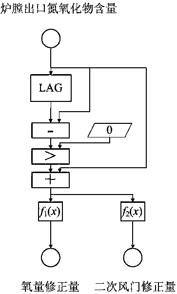
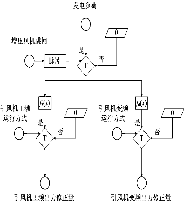
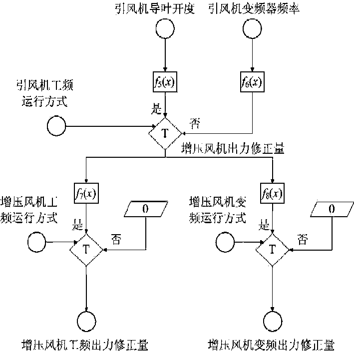
[0025] Step 1: Add the following control loops and loop interfaces to the control logic configuration of the DCS of the thermal power unit's distributed control system: the oxygen correction amount control loop and loop interface after the thermal power plant's desulfurization and denitrification transformation, and the second after the thermal power plant's desulfurization and denitrification transformation. Secondary air door opening correction amount control loop and loop interface, induced draft fan output correction amount control loop and loop interface after thermal power plant desulfurization and denitration transformation, and booster fan output correction amount control loop and loop interface after thermal power plant desulfurization and denit...


PUM


Abstract

The invention relates to an optimizing method of air and flue gas system control after desulfurization and denitrification transformation of a thermal power generating unit. An oxygen amount allowancecontrol loop after desulfurization and denitrification transformation of the thermal power generating unit and a loop interface, a secondary air valve opening degree allowance control loop after desulfurization and denitrification transformation of the thermal power generating unit and a loop interface, an induced draft fan output allowance control loop after desulfurization and denitrification transformation of the thermal power generating unit and a loop interface as well as a booster fan output allowance control loop after desulfurization and denitrification transformation of the thermal power generating unit and a loop interface are additionally arranged in the control logical configuration of a thermal power generating unit distributed control system (DCS); air blower output interlocking control logic and secondary air valve opening degree interlocking control logic after desulfurization and denitrification transformation of the thermal power generating unit are added in the control logical configuration of the thermal power generating unit DCS; according to the real-time running curve of the control system, related parameters of various control loops for optimization of airand flue gas system control after desulfurization and denitrification transformation of the thermal power generating unit are adjusted online, and the expected control effect is realized finally. Theproblem about automatic air and flue gas system control after desulfurization and denitrification transformation of the thermal power generating unit is solved, the equipment potential is fully played, and the stability of main parameters is guaranteed.

Description

Technical field [0001] The invention belongs to the technical field of automatic control of thermal power generating units, and in particular relates to a method for optimizing the control of air and smoke systems of thermal power generating units after desulfurization and denitration transformation. It can be used for automatic control of oxygen content, automatic control of secondary air door, automatic control of induced draft fan, automatic control of booster fan of thermal power unit in the actual operation process, to ensure that the unit is in operation, through the distributed control system DCS to automatically oxidize the furnace outlet nitrogen Material and furnace pressure are controlled within a reasonable range. Background technique [0002] With the increasingly stringent environmental protection requirements, coal-fired power generation companies have carried out energy-saving and emission-reduction transformations and upgrades to coal-fired units, including addin...

Claims


Application Information

Patent Timeline
Patent Type & Authority Patents(China)
IPC IPC(8): F23N3/00
CPCF23N3/002F23N2900/05003
Inventor 姚远戴黎李建军李根宋圣军张天放胡绍宇付宇邵毅毕徳忠
Owner STATE GRID LIAONING ELECTRIC POWER RES INST
Why Eureka
Try Eureka