Efficient drying conveying belt

A conveyor belt and drying technology, applied in the field of conveyor belts, can solve problems such as low drying efficiency and waste heat, and achieve the effects of easy removal and cleaning, energy saving and production environment improvement.

Pending Publication Date: 2018-04-20
成都顺宏鑫机械有限公司
View PDF16 Cites 1 Cited by
  • Summary
  • Abstract
  • Description
  • Claims
  • Application Information

AI Technical Summary

Problems solved by technology

[0003] The purpose of the present invention is to provide a high-efficiency drying conveyor belt to solve the problem that the existing drying conveyor belt can only blow and dry one side of the object, resulting in low drying efficiency and waste heat in the drying process

Method used


Image

  • Efficient drying conveying belt

Examples


Embodiment 1

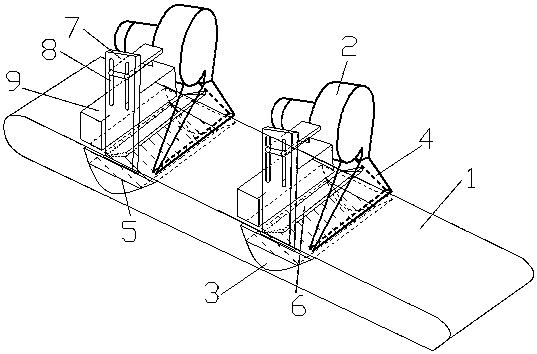
[0017] The high-efficiency drying conveyor belt includes a conveyor belt 1 driven by a motor, a hot air blower 2, and an air source heat pump 9. The conveyor belt 1 is a mesh belt with holes. Above the conveyor belt 1, a U-shaped groove 3 is arranged on the body below the uplink surface of the conveyor belt 1. Corresponding to the side, the air inlet of the hot air blower 2 is provided with a condenser, and the condenser is connected with the air energy heat pump 9 .

[0018] The object is transported on the conveyor belt, and the hot air generated by the hot air blower is blown downward from the air outlet to dry the upper surface of the object, and then passes through the hole on the conveyor belt 1, enters the U-shaped groove from the side of the U-shaped groove, and passes through the U-shaped groove. Under the guidance of the guide, it blows upward from the other side of the U-shaped groove to dry the bottom surface of the object, making the drying more uniform and more e...

Embodiment 2

[0020] The high-efficiency drying conveyor belt includes a conveyor belt 1 driven by a motor, a hot air blower 2, and an air source heat pump 9. The conveyor belt 1 is a mesh belt with holes. Above the conveyor belt 1, a U-shaped groove 3 is arranged on the body below the uplink surface of the conveyor belt 1. Corresponding to the side, the air inlet of the hot air blower 2 is provided with a condenser, and the condenser is connected with the air energy heat pump 9 . The two ends of the U-shaped groove 3 are opened, and a slide rail is arranged in the U-shaped groove 3. The slide rail is from one end of the U-shaped groove 3 to the other end of the U-shaped groove 3. The oil filter 5 is arranged through the slide rail in the U-shaped groove 3 to prevent oil pollution. The surface of filter screen 5 is wrapped with oil-absorbing felt. Prevent the oil stain of the dry matter from dripping in the U-shaped groove 3, and the setting of the slide rail is convenient for the oil filt...

Embodiment 3

[0023] The high-efficiency drying conveyor belt includes a conveyor belt 1 driven by a motor, a hot air blower 2, and an air source heat pump 9. The conveyor belt 1 is a mesh belt with holes. Above the conveyor belt 1, a U-shaped groove 3 is arranged on the body below the uplink surface of the conveyor belt 1. Corresponding to the side, the air inlet of the hot air blower 2 is provided with a condenser, and the condenser is connected with the air energy heat pump 9 . A moisture absorber is arranged in the hot air blower 2 near the air inlet. There is water vapor in the air, especially after the object is dried, there will be more water vapor in the air. The moisture absorber absorbs the water vapor and then blows it out after being heated by the hot air blower to ensure the drying efficiency. The two ends of the U-shaped groove 3 are opened, and a slide rail is arranged in the U-shaped groove 3. The slide rail is from one end of the U-shaped groove 3 to the other end of the U...


PUM


Abstract

The invention relates to a conveying belt, in particular to an efficient drying conveying belt. The efficient drying conveying belt comprises a conveying belt (1) driven by a motor, an air heater (2)and an air energy heat pump (9); the conveying belt (1) is a net belt with holes; the air energy heat pump (9) and the air heater (2) are mounted above the conveying belt (1) in sequence in a conveying direction; a U-shaped groove (3) is formed in a machine body below an upward belt surface of the conveying belt (1); an air sucking port of the air energy heat pump (9) is corresponding to the frontside of the U-shaped groove (3); an exhaust port of the air heater (2) is corresponding to the back side of the U-shaped groove (3); a condenser is arranged in an intake port of the air heater (2); and the condenser is connected with the air energy heat pump (9). The efficient drying conveying belt can dry two surfaces of objects, and uses the air energy heat pump (9) for absorbing afterheat andheat in air to save energy.

Description

technical field [0001] The invention relates to a conveyor belt, in particular to a high-efficiency drying conveyor belt. Background technique [0002] The existing hot air drying conveyor belt uses a hot air blower to cooperate with the conveyor belt. The objects are transported on the conveyor belt. The hot air blower blows hot air to the object to dry. One hot air blower can only blow and dry one of the surfaces of the object, so the drying is uneven and the efficiency is low. , and in this process, a large amount of heat in the hot air is not used, it is wasted, and it is extremely energy-saving. Contents of the invention [0003] The purpose of the present invention is to provide a high-efficiency drying conveyor belt to solve the problem that the existing drying conveyor belt can only blow dry one side of the object, resulting in low drying efficiency and waste heat in the drying process. [0004] In order to solve the above-mentioned technical problems, the present...

Claims


Application Information

Patent Timeline
Patent Type & Authority Applications(China)
IPC IPC(8): F26B15/18F26B21/00F26B23/00F26B25/18F26B25/00
CPCF26B15/18F26B21/001F26B23/00F26B25/00F26B25/18
Inventor 兰君
Owner 成都顺宏鑫机械有限公司
Why Eureka
Try Eureka