Electrostatic discharge protection circuit, integrated circuit chip and electronic equipment
An electrostatic discharge protection and circuit technology, applied in circuits, electrical components, electric solid devices, etc., can solve the problems of ESD protection failure and other problems, achieve the effect of improving ESD protection level, good ESD protection level, and reducing gate potential
- Summary
- Abstract
- Description
- Claims
- Application Information
AI Technical Summary
Problems solved by technology
Method used
Image

Examples
Embodiment 1
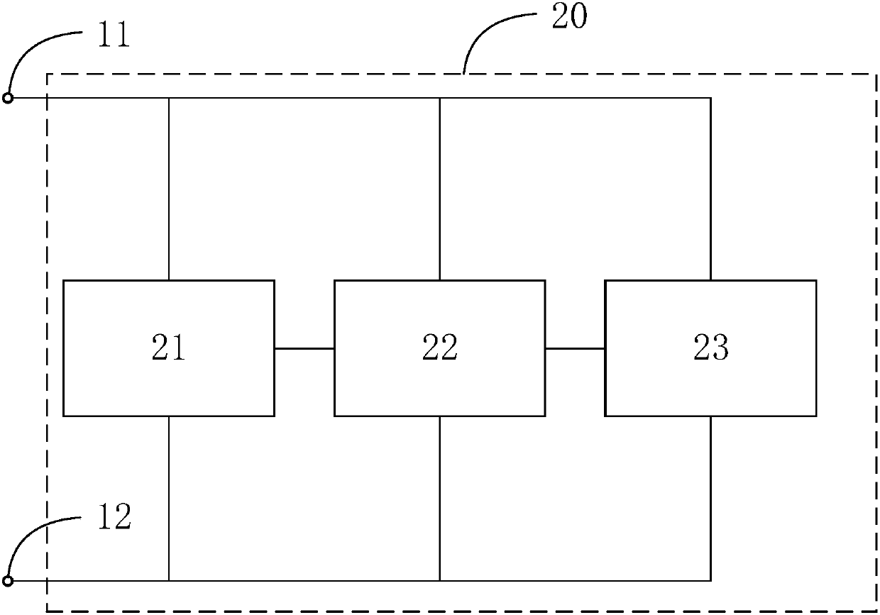
[0049] Please refer to figure 2 , which shows a schematic diagram of an electrostatic discharge protection circuit provided by Embodiment 1 of the present invention. like figure 2 As shown, the electrostatic discharge protection circuit 20 includes: a transient circuit 21, a voltage divider circuit 22 and a gate drive discharge device 23 connected in parallel between the power pin 11 and the ground pin 12 and sequentially coupled;
[0050]When the transient circuit 21 detects static electricity, the voltage divider circuit 22 is triggered to send a driving signal whose voltage value is less than the power supply voltage value to the gate of the gate drive discharge device 23, and the gate drive discharge device 23 is at the gate. Driven by the above drive signal to discharge static electricity.
[0051] Specifically, the transient circuit 21 is used to detect static electricity. When an electrostatic discharge occurs, a high-voltage pulse will be generated at the power int...
Embodiment 2
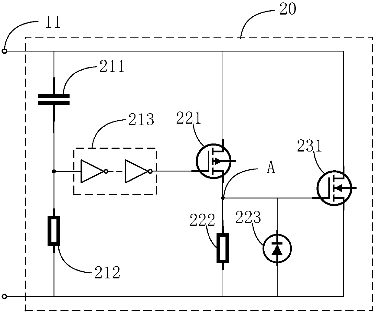
[0056] Please refer to image 3 , which shows a schematic diagram of an electrostatic discharge protection circuit provided in Embodiment 2 of the present invention. The electrostatic discharge protection circuit provided in Embodiment 2 of the present invention is implemented on the basis of Embodiment 1, and part of the content will not be repeated here. , please understand it in conjunction with the description of the above-mentioned part of the embodiment, such as image 3 As shown, the electrostatic discharge protection circuit 20 includes: a transient circuit 21 connected in parallel between the power supply pin 11 and the ground pin 12, a voltage divider circuit 22 and a gate drive discharge device 23;
[0057] The transient circuit 21 includes: a capacitor 211, a first resistor 212 and an inverter group 213;
[0058] The voltage dividing circuit 22 includes: a first PMOS transistor 221 and a second resistor 222;
[0059] The gate drive bleeder device 23 includes: a f...
Embodiment 3
[0073] Please refer to Figure 4 , which shows a schematic diagram of an electrostatic discharge protection circuit provided by Embodiment 3 of the present invention. The electrostatic discharge protection circuit provided by Embodiment 3 of the present invention is implemented on the basis of Embodiment 2, and part of the content will not be repeated. , please understand it in conjunction with the description of the second part of the above embodiment, Figure 4 The ESD protection circuit shown with image 3 Compared with the electrostatic discharge protection circuit shown, the structure of the voltage divider circuit 22 and the gate drive discharge device 23 are consistent, and there are differences in the transient circuit 21, such as Figure 4 As shown, the transient circuit 21 includes: a capacitor 211, a first resistor 212 and an inverter group 213;
[0074] The first end of the first resistor 212 is connected to the power supply pin 11, the first end of the capacitor...
PUM
 Abstract
Description
Claims
Application Information
 - R&D
- Intellectual Property
- Life Sciences
- Materials
- Tech Scout
- Unparalleled Data Quality
- Higher Quality Content
- 60% Fewer Hallucinations
Browse by: Latest US Patents, China's latest patents, Technical Efficacy Thesaurus, Application Domain, Technology Topic, Popular Technical Reports.
© 2025 PatSnap. All rights reserved.Legal|Privacy policy|Modern Slavery Act Transparency Statement|Sitemap|About US| Contact US: help@patsnap.com