Battery pack

A battery pack, battery technology, applied in batteries, battery pack components, secondary batteries, etc., can solve problems such as heat accumulation

Active Publication Date: 2018-04-20
DENSO CORP
View PDF6 Cites 5 Cited by
  • Summary
  • Abstract
  • Description
  • Claims
  • Application Information

AI Technical Summary

Problems solved by technology

In addition, when the fan is not working, there is no air circulation around the car battery, which creates a problem of heat accumulation

Method used


Image

  • Battery pack
  • Battery pack
  • Battery pack

Examples


Embodiment approach 1

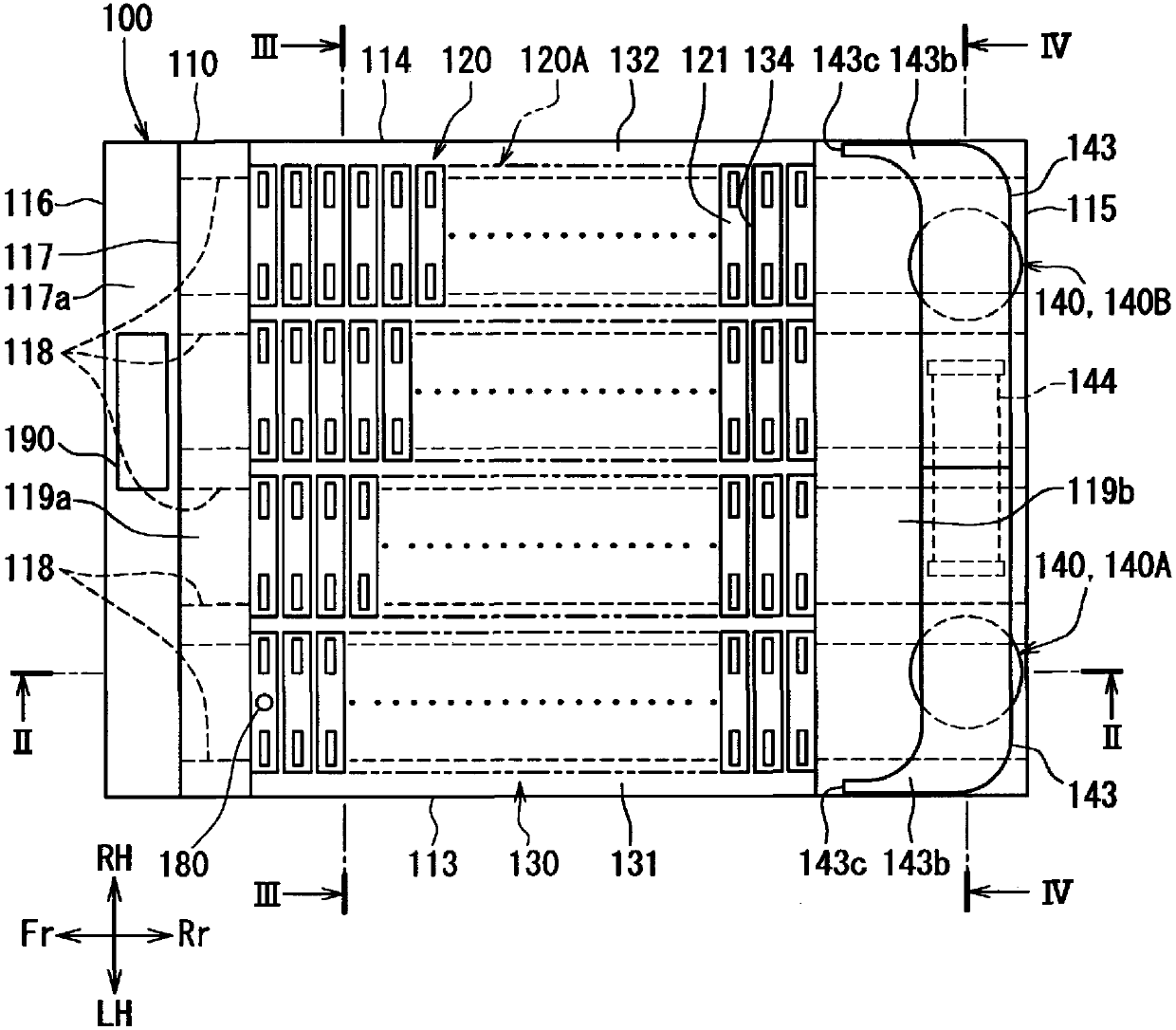
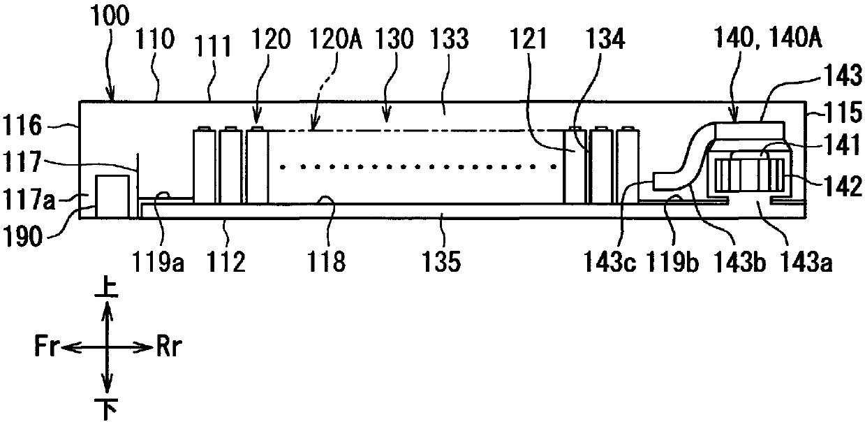
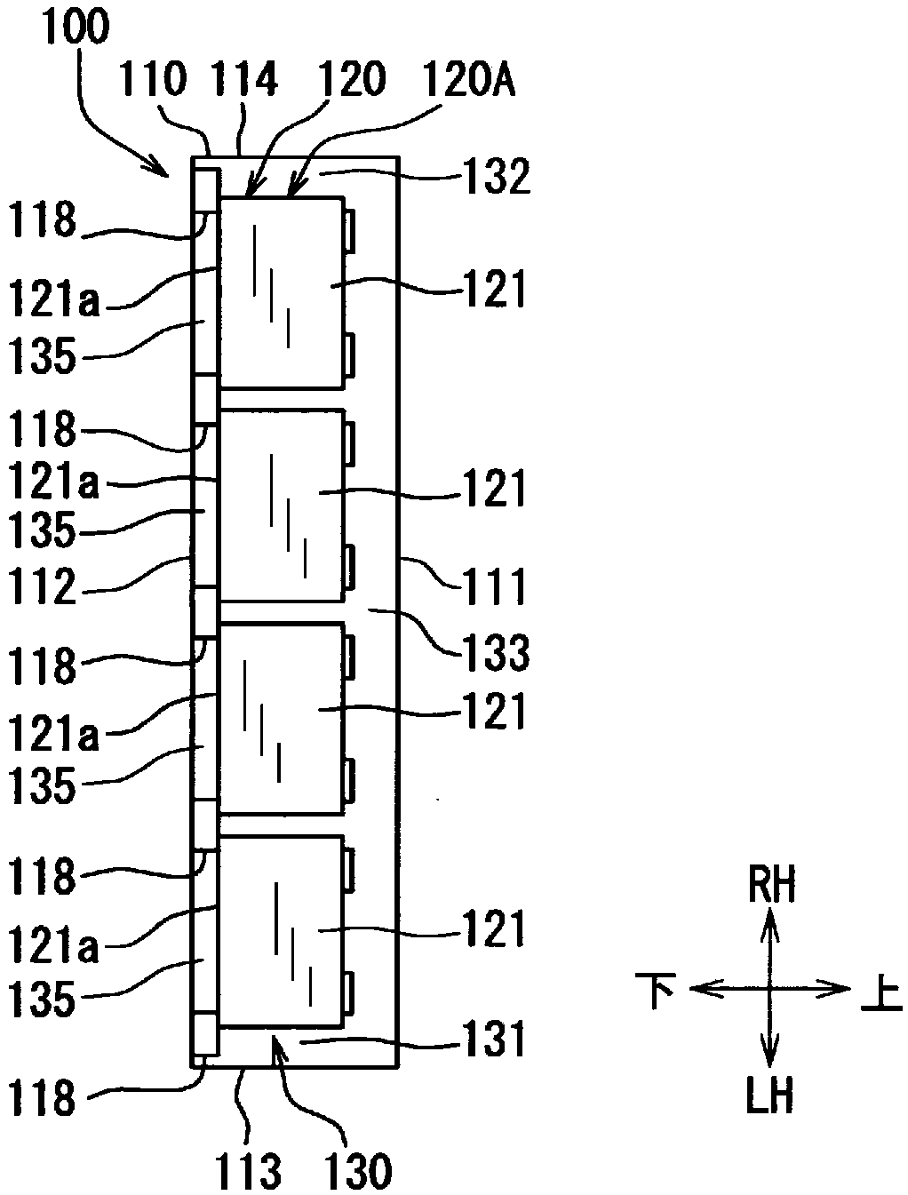
[0038] refer to Figure 1 to Figure 7 , the configuration of the battery pack 100 according to Embodiment 1 as an example of the present invention will be described. The assembled battery 100 is applicable, for example, to a hybrid vehicle driven by an electric motor driven by electric power charged in a battery, an internal combustion engine, or an electric vehicle driven by a motor. The plurality of unit batteries 121 included in the battery pack 100 are, for example, nickel-metal hydride rechargeable batteries, lithium-ion rechargeable batteries, organic batteries, and the like.

[0039] The battery pack 100 is installed in a battery pack storage space such as a trunk of a vehicle or an area inside the trunk below the trunk. The battery pack storage space can also store a spare tire, tools, and the like, for example. The battery pack 100 is installed in the battery pack storage space with a bottom wall 112 or a bottom wall-side passage 135 , which will be described later,...

Embodiment approach 2

[0143] The content of the control executed by the battery management unit 190 in Embodiment 2 is given by Figure 14 , Figure 15 to show. In Embodiment 2, as compared to Embodiment 1 described above, when the cooling rotation speed N1 and the heating rotation speed N3 are increased according to the battery temperature T, the cooling rotation speed N1 and the heating rotation speed N3 are changed stepwise.

[0144] In the battery management unit 190 , required cooling temperatures Tc2 , Tc3 , and Tc4 are preset in addition to the required cooling temperature Tc1 as predetermined determination values ​​for determining whether the unit cells 121 need to be cooled. The respective cooling required temperatures Tc1 to Tc4 have a magnitude relationship of Tc1

[0145] In addition, in the cooling mode, N11, N12, N13, and N14 are set in advance as cooling rotation speeds when the air blowers 140A, 140B are operated. T...


PUM


Abstract

This battery pack has a plurality of batteries and a blower stored in the housing, and causes a control unit to manage the temperature of the plurality of batteries in accordance with the battery temperature detected by a temperature detector. When the battery temperature rises to more than or equal to a predetermined cooling required temperature Tc1, the control unit implements a cooling mode where the blower is operated to cool the plurality of batteries. The control unit implements a temperature equalization mode where the blower is operated to equalize the temperature in the housing with afluid flowing through a circulation passage even if cooling is unnecessary because the battery temperature T is lower than the cooling required temperature Tc1.

Description

technical field [0001] The present invention relates to a battery pack having a plurality of unit cells housed inside a case. Background technique [0002] Conventionally, for example, a battery pack described in Patent Document 1 is known. The battery pack described in Patent Document 1 is a control device for a fan used to cool a vehicle-mounted battery. The on-vehicle battery supplies power to an electric motor serving as a drive source for traveling, and is disposed, for example, under a passenger seat. In addition, a fan for cooling the on-vehicle battery is provided at a position adjacent to the on-vehicle battery. The action of the fan is controlled by the control device. The cooled air in the cabin is supplied to the on-vehicle battery by the operation of the fan. [0003] Then, in Patent Document 1, the control device operates a fan to cool the on-vehicle battery when the temperature of the on-vehicle battery reaches a predetermined A level or higher. At this t...

Claims


Application Information

Patent Timeline
Patent Type & Authority Applications(China)
IPC IPC(8): H01M10/633H01M10/48H01M10/613H01M10/615H01M10/617H01M10/625H01M10/647H01M10/651H01M10/6551H01M10/6563H01M10/6571H01M10/663H01M50/209
CPCH01M10/48H01M10/625H01M10/615H01M10/633H01M10/6563H01M10/6571H01M10/617H01M10/651H01M10/613Y02T10/70B60L2240/662B60L58/26B60L2240/545B60L50/64Y02E60/10H01M2220/20H01M50/249Y02T10/72Y02T90/16H01M50/209B60L58/27
Inventor 加藤真也佐田岳士井上美光山本启善井口翔太
Owner DENSO CORP
Why Eureka
Try Eureka