Automobile engine crankshaft timing tooling and crankshaft timing and positioning method

A technology of automobile engine and crankshaft journal, which is applied in the fields of automobile engine crankshaft timing tooling and crankshaft timing positioning, which can solve problems such as inaccurate positioning of the crankshaft center hole, broken positioning pins, and affecting strength, so as to avoid deviation, It can withstand large torque and is not easy to damage the crankshaft

Inactive Publication Date: 2018-04-24
宁波美佳宁生物科技有限公司
View PDF8 Cites 9 Cited by
  • Summary
  • Abstract
  • Description
  • Claims
  • Application Information

AI Technical Summary

Problems solved by technology

[0003] The timing positioning is checked by the naked eye to see if the mark on the magneto rotor coincides with the mark on the observation hole of the engine side cover. There is a large error, and manual or temporary tools are used to prevent the magneto from rotating, so it cannot be guaranteed that the crankshaft will be installed when the rest of the timing system parts are installed. The timing position is stable, and there is a large deviation in crankshaft timing positioning using this method
[0004] The Chinese patent with the patent number CN201420675977.9 discloses a crankshaft timing positioning tool, but the disclosed tool utilizes the center hole of the engine crankshaft and the threaded hole at the rear end of the crankshaft for positioning. The center hole of the engine crankshaft is a prefabricated hole. After machining, the crankshaft positioning center is the outer circle of the crankshaft journal. The crankshaft center hole is not accurate in positioning. Generally, the threaded hole at the rear end of the crankshaft does not require high machining positions. It is not accurate to use it as a positioning reference, and the center hole is generally a tapered hole. The positioning is inconvenient. The crankshaft timing positioning tool disclosed in the above-mentioned patent is made of aluminum, and the tool itself has low strength. When the engine is installed with the timing system, the installation torque of the sprocket fastening bolts reaches 60-80N·m. The tooling is easily deformed and damaged, and needs to be replaced in a short period of time. The cost of use is high, and aluminum tooling requires high costs whether it is machined from aluminum blocks or made by die-casting aluminum. The processing accuracy of aluminum products Low, can not fully meet the accuracy required for tooling positioning
[0005] The Chinese patent with the patent number CN201510486601.2 discloses a tooling assembly for accurately installing the crankshaft timing gear. The key grooves on the shaft journals need to be processed separately. Generally, crankshafts only have crankshaft key grooves processed on the first and second journals, and some only have key grooves processed on one journal. Therefore, it is necessary to use the tooling disclosed in this invention. , the crankshaft needs to be reprocessed or redeveloped, the cost is high, and the crankshaft intermediate journal is the main force-bearing part when the engine is working, setting the keyway on the intermediate journal will affect its strength and increase the risk of engine failure; When the invention is used for positioning, observe whether the pointer is aligned with the center line of the crankshaft. Since the staff observes with the naked eye, errors inevitably exist. Because the ability of the operator is high or low, the staff with poor ability is using the crankshaft described in the present invention. When the tooling is operated, the error is relatively large, and the tooling itself takes up a lot of space for positioning, which affects the installation of other timing system components; the invention discloses a tooling component structure for accurately installing the crankshaft timing gear It is more complicated, there are many long rod-shaped structures, and it is difficult to process under the condition of ensuring a certain accuracy requirement. After the tooling is used for a long time, the positioning accuracy of the tooling cannot be guaranteed.
[0006] The Chinese patent with the patent number CN201410302881.2 discloses a crankshaft timing tool and a crankshaft timing positioning method. The crankshaft timing tool uses the positioning pin hole on the crankshaft end flange for positioning, but most engines do not have a crankshaft End flange plate structure, using this method for crankshaft timing positioning, it is necessary to add parts such as crankshaft end flange plate. The diameter of the positioning pin hole on the disk is small. Use this positioning pin hole for positioning. When installing subsequent parts, a larger torque is applied to the positioning pin with a smaller diameter on the tooling, which will easily cause the positioning pin to break, not only damage the tooling, In severe cases, the crankshaft components may be damaged. Since the crankshaft is an important part of the engine, damage to the crankshaft components will directly lead to engine failure

Method used


Image

  • Automobile engine crankshaft timing tooling and crankshaft timing and positioning method
  • Automobile engine crankshaft timing tooling and crankshaft timing and positioning method
  • Automobile engine crankshaft timing tooling and crankshaft timing and positioning method

Examples


Embodiment 1

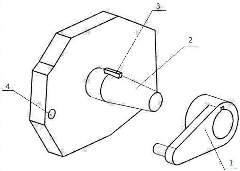
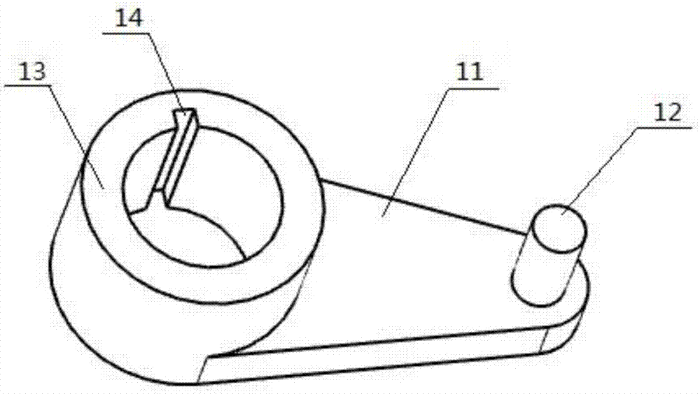
[0037] Such as figure 1 and figure 2 The shown crankshaft timing tooling 1 includes a tooling plate 11, one end of the tooling plate is a cylindrical sleeve 13, the inner hole of the cylindrical sleeve 13 matches the outer circle of the journal of the crankshaft 2, and the inner hole of the cylindrical sleeve 13 A key groove 14 matched with the semicircular key 3 on the journal of the crankshaft 2 is provided, and the other end of the tooling plate 11 is a positioning pin cylinder 12 matched with the crankcase positioning pin hole 4 . The relative position of the keyway 14 in the cylindrical sleeve 13 and the dowel pin cylinder 12 is when the automobile engine crankshaft 2 is in the correct timing position, the relative position of the semicircle key 3 on the crankshaft 2 and the crankcase dowel hole 4. The material of the crankshaft timing tooling 1 is No. 45 steel, which is cheap and easy to process. It has good performance after high-frequency quenching in the later stage...

Embodiment 2

[0048] Such as Figure 6 The shown crankshaft timing tool 1 differs from the crankshaft timing tool described in Embodiment 1 in that the connection between the positioning pin cylinder 12 and the tooling plate 11 is a flexible connection, and the tooling plate 11 is provided with a through hole 15. The positioning pin cylinder 12 passes through the through hole 15 and slides in the through hole 15. The crankshaft timing tool 1 described above can be used for a vehicle engine with a relatively compact structure and limited space during assembly. The shown crankshaft timing tooling 1 carries out the method steps of crankshaft timing positioning as follows:

[0049] (1) Turn the crankshaft 2, so that the piston reaches near the top dead center;

[0050] (2) Install the half-round key 3 in the crankshaft 1 journal keyway;

[0051] (3) Put the cylindrical sleeve 13 at one end of the crankshaft timing tool 1 on the crankshaft 2, and make the semicircular key 3 on the crankshaft 2...


PUM


Abstract

The invention discloses an automobile engine crankshaft timing tooling and a crankshaft timing and positioning method. The crankshaft timing tooling comprises a tooling plate, a cylindrical sleeve anda positioning pin column, the cylindrical sleeve is arranged at one end of the tooling plate, an inner hole of the cylindrical sleeve is matched with an external circle of a crankshaft journal, a keyslot matched with a woodruff key on the crankshaft journal is formed in the inner hole of the cylindrical sleeve, and the other end of the tooling plate is connected with the positioning pin column matched with a positioning pin hole in a crankshaft case. According to the tooling, crankshaft timing positions can be accurately positioned, a crankshaft and the crankshaft case are relatively fixed,a timing system is conveniently installed, and installation accuracy of the timing system is improved. The crankshaft timing and positioning method is simple and easy and avoids large errors caused byvisual inspection of scale marks for positioning in a traditional timing method, the position of the crankshaft is limited while the crankshaft is positioned, rotation of the crankshaft is prevented,and crankshaft timing position stability is ensured when other parts of the timing system are installed.

Description

technical field [0001] The invention relates to the technical field of automobile engine assembly, in particular to an automobile engine crankshaft timing tool and a crankshaft timing positioning method. Background technique [0002] The engine timing system of a car is related to the stability of the engine operation. If the accuracy of the engine timing system is not good, it will affect the normal operation of the engine, resulting in reduced engine performance or even failure to work. The traditional installation method of automobile engine timing is to firstly fix the magneto rotor to the crankshaft through the lock nut, the magneto rotor and the crankshaft journal are angularly positioned through the half-round key, the engine side cover is installed, and the magneto rotor is rotated by tools to make the The mark on the rotor coincides with the mark on the observation hole on the side cover, use manual or temporary tools to stop the magneto from rotating, and install t...

Claims


Application Information

Patent Timeline
Patent Type & Authority Applications(China)
IPC IPC(8): B25B27/00
Inventor 王坚屏
Owner 宁波美佳宁生物科技有限公司
Why Eureka
Try Eureka