Motor cover accommodating equipment
A motor cover and equipment technology, applied in coatings, anti-corrosion coatings, polyester coatings, etc., can solve the problems of troublesome motor cover transportation, waste of time and resources, recycling, processing and scrapping, etc., and achieves convenient operation, convenient use, and improved service life. Effect
- Summary
- Abstract
- Description
- Claims
- Application Information
AI Technical Summary
Problems solved by technology
Method used
Image

Examples
Embodiment 1
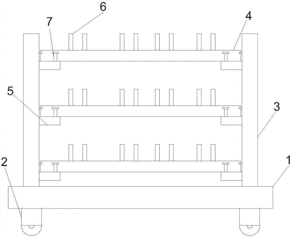
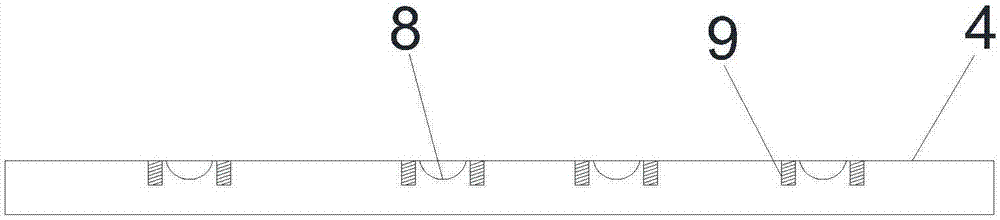
[0052] like figure 1 , figure 2 as well as image 3 As shown, a device for placing a motor cover includes a bottom plate 1, a roller 2 is connected to the bottom of the bottom plate 1, a placement frame 3 is provided above the bottom plate 1, and a placement plate 4 is arranged inside the placement frame 3, and the placement plate 4 passes through The fixed platform 5 is connected on the placement frame 3, the placement plate 4 is provided with a placement groove 8, the placement groove 8 is provided with a positioning rod 6, and the placement plate 4 is provided with a through hole 9;
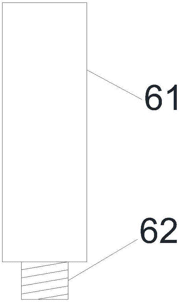
[0053] The positioning rod 6 is provided with two parts, one part is a threaded joint 62, and the other part is a supporting part 61;
[0054] The roller 2 is connected under the bottom plate 1 by means of screw fastening or welding, and the roller 2 is a universal wheel;
[0055] The fixed table 5 is welded on the placement frame 3, and the fixed table 5 is provided with a connection hole...
Embodiment 2
[0059] The isolation coating used on the placement board is made of the following materials in parts by weight,
[0060] 14-20 parts of resin, 9 parts of silane coupling agent KH-5306, 2-7 parts of propylene glycol butyl ether, 3-9 parts of oxalic acid, 8-14 parts of modified activated carbon, 6-10 parts of antimony trioxide, ethyl acrylate 4-10 parts of ester, 1-6 parts of fatty alcohol polyoxyethylene ether, 9-14 parts of biological aid, 5-11 parts of anti-aging agent, 25-31 parts of clear water;
[0061] The resin is one of polyvinyl chloride resin, polyimide resin, phenolic resin, and alkyd resin;
[0062] Described anti-aging agent is the one in anti-aging agent A, anti-aging agent D, anti-aging agent RD, anti-aging agent IPPD;
[0063] The preparation method of the modified activated carbon is as follows: Grind the activated carbon and pass through a 400-500 mesh sieve, then bake it at a temperature of 45°C for 30 minutes, then add 0.8 times its mass of pure water at 60...
Embodiment 3
[0074] like figure 1 , figure 2 as well as image 3 As shown, a device for placing a motor cover includes a bottom plate 1, a roller 2 is connected to the bottom of the bottom plate 1, a placement frame 3 is provided above the bottom plate 1, and a placement plate 4 is arranged inside the placement frame 3, and the placement plate 4 passes through The fixed platform 5 is connected on the placement frame 3, the placement plate 4 is provided with a placement groove 8, the placement groove 8 is provided with a positioning rod 6, and the placement plate 4 is provided with a through hole 9;
[0075] The positioning rod 6 is provided with two parts, one part is a threaded joint 62, and the other part is a supporting part 61;
[0076] The roller 2 is connected under the bottom plate 1 by means of screw fastening or welding, and the roller 2 is a universal wheel;
[0077] The fixed table 5 is welded on the placement frame 3, and the fixed table 5 is provided with a connection hole...
PUM
 Abstract
Description
Claims
Application Information
 - R&D
- Intellectual Property
- Life Sciences
- Materials
- Tech Scout
- Unparalleled Data Quality
- Higher Quality Content
- 60% Fewer Hallucinations
Browse by: Latest US Patents, China's latest patents, Technical Efficacy Thesaurus, Application Domain, Technology Topic, Popular Technical Reports.
© 2025 PatSnap. All rights reserved.Legal|Privacy policy|Modern Slavery Act Transparency Statement|Sitemap|About US| Contact US: help@patsnap.com