Implant conveying system and using method thereof

A delivery system and implant technology, applied in the field of medical devices, can solve problems such as long time required to form a circuit, increase the difficulty of surgical operation, and poor user experience, so as to reduce surgical pain, time-consuming, stable, and cost-effective short-term effect

Pending Publication Date: 2018-04-27
MICROPORT NEUROTECH SHANGHAI
View PDF0 Cites 3 Cited by
  • Summary
  • Abstract
  • Description
  • Claims
  • Application Information

AI Technical Summary

Problems solved by technology

[0007] The purpose of the present invention is to provide an implant delivery system and its use method, in order to solve the problem of releasing the implant from the push rod, it is necessary to insert the conductive needle into the patient's skin, so that the push rod and the conductive needle form a loop, and there is a need to form a loop. The time is long and unstable, and the user experience effect is not good, which increases the difficulty of surgical operation

Method used


Image

  • Implant conveying system and using method thereof
  • Implant conveying system and using method thereof
  • Implant conveying system and using method thereof

Examples


Embodiment 1

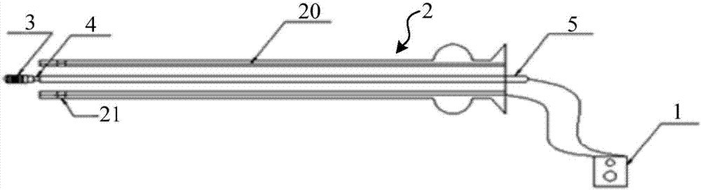
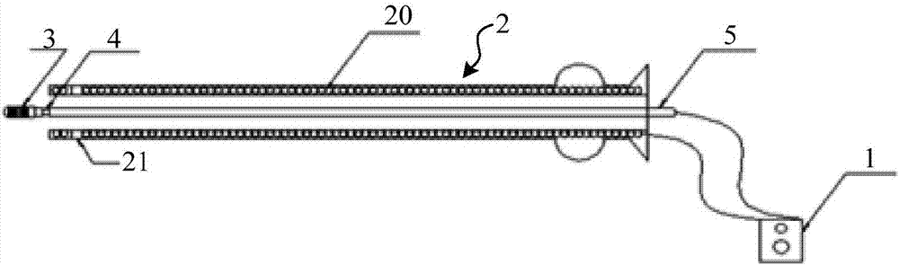
[0037] Please refer to Figure 2-Figure 4 , which is a schematic structural view of the implant delivery system of the present invention, such as Figure 2-Figure 4 As shown, the implant delivery system includes: a releaser 1, an electrolysis component 4, a push rod 5 and a microcatheter 2, and the implant 3, the electrolysis component 4 and the push rod 5 are sequentially connected and accommodated in the In the microcatheter 1, the implant 3 delivery system also includes a conductive layer 20 arranged on the microcatheter 2, an electrode end of the releaser 1 is electrically connected to the push rod 5, and the releaser The other electrode terminal of 1 is electrically connected to the conductive layer 20 .

[0038] In this example, if Figure 2-Figure 4 As shown, the micro-catheter 2 includes at least two layers of pipe walls, the conductive layer 20 is arranged in the interlayer between the at least two layers of pipe walls, and the outer surface or inner surface of the ...

Embodiment 2

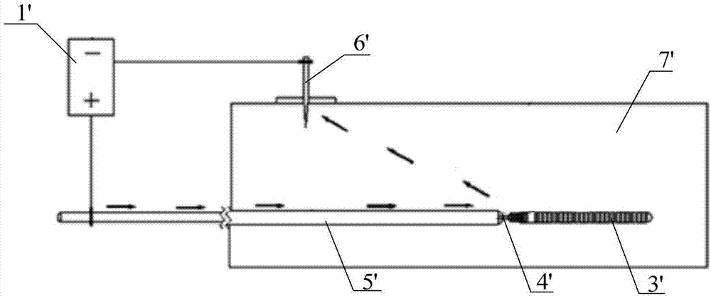
[0047] Correspondingly, this embodiment also provides a method for using the implant delivery system. Refer below Image 6 and Figure 1-4 The method of using the implant delivery system described in this embodiment will be described in detail.

[0048] Firstly, step S1 is performed to transport the distal end of the microcatheter 2 to a predetermined location (such as an aneurysm lesion location), and the predetermined location is in an ionic solution 7' ​​(such as blood or other body fluids).

[0049] Next, step S2 is executed, controlling the push rod 5 to push the electrolytic component 4 and the implant 3 through the microcatheter 2 until the electrolytic component 4 and the implant 3 pass through the microcatheter 2 The distal end of the catheter 2 passes out and is exposed to the ionic solution 7'.

[0050] Next, step S3 is executed to start the releaser 1 , and a loop is formed between the conductive layer 20 and the push rod 5 .

[0051] Next, step S4 is executed,...


PUM


Abstract

The invention provides an implant conveying system and a using method thereof. The implant conveying system comprises a release unit, an electrolysis part, a push rod and a micro-catheter, as well asa conducting layer which is arranged on the micro-catheter, wherein an electrode end of the release unit is electrically connected to the push rod; and another electrode end of the release unit is electrically connected to the conducting layer. By adding the conducting layer on the micro-catheter as an electrode end which is required by implant release, an implant is conveyed by virtue of the micro-catheter, and meanwhile, the conducting layer, which functions as the electrode end, is conveyed into an ion solution; when the electrolysis part gets into contact with the ion solution and the release unit is electrified, a loop is defined between the conducting layer and the push rod, and the electrolysis part conducts electrolysis in the ion solution, so that the implant is released from thepush rod. According to the implant conveying system provided by the invention, harm of a conducting needle, which functions as the electrode end, to a patient is avoided, and operation pain is relieved; moreover, due to the defined loop, consumed time is shortened and stability is guaranteed, so that the release efficiency of the implant is improved; and meanwhile, the additional use of the conducting needle is avoided, and operations are further simplified.

Description

technical field [0001] The invention relates to the technical field of medical devices, in particular to an implant delivery system and a method for using the same. Background technique [0002] An aneurysm is a local weakness caused by disease, injury or congenital factors. Under the impact of long-term blood flow, the weak point of the arterial wall protrudes outwards and gradually expands to form a round, oval or prismatic sac bulging. [0003] There are many methods for interventional treatment of intracranial aneurysms, mainly including vascular reconstruction on the parent artery with dense mesh stenting and embolization in the aneurysm cavity. Embolization of implants (such as spring coils) in the aneurysm cavity is currently the main method for treating aneurysms. [0004] In 1991, Guglielmi et al first reported GDC embolization for the treatment of intracranial aneurysms. The implant at the distal end of the GDC is made of platinum, which is connected to the push...

Claims


Application Information

Patent Timeline
Patent Type & Authority Applications(China)
IPC IPC(8): A61B17/12
CPCA61B17/12113A61B17/1214A61B2017/12063
Inventor 陈冰郭远益彭云飞倪尊张金巧蓉谢志永
Owner MICROPORT NEUROTECH SHANGHAI
Why Eureka
Try Eureka