Ejection ball system and conveying system

A technology of ejecting material and input end, which is applied in the field of ejecting ball system and transmission system, can solve the problem of liquid residue in the pipeline, and achieve the effect of reducing dosage, saving wine loss, and reducing CIP time.

Pending Publication Date: 2018-04-27
武汉博亚德自动化工程有限公司
View PDF0 Cites 0 Cited by
  • Summary
  • Abstract
  • Description
  • Claims
  • Application Information

AI Technical Summary

Problems solved by technology

[0002] Existing pipes in most filling lines will have liquid residue

Method used


Image

  • Ejection ball system and conveying system
  • Ejection ball system and conveying system
  • Ejection ball system and conveying system

Examples


no. 1 example

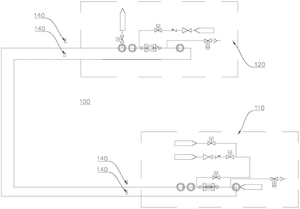
[0031] Please refer to Figure 1 to Figure 4 , the present embodiment provides a ball ejecting system 100 , which includes a launching station 110 , a recycling station 120 , a controller 130 , a position sensor 140 and a display screen 150 .

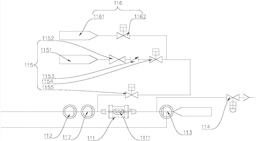
[0032]The launch station 110 includes a first observation window 111 , a first valve 112 , a second valve 113 , a first outlet valve 114 and a first carbon dioxide feeder 115 .

[0033] In this embodiment, the input end of the first observation window 111 is connected to the output end of the first valve 112 , and the output end of the first observation window 111 is connected to the input end of the second valve 113 . Wherein, the first observation window 111 may be connected to the first valve 112 and the second valve 113 through connecting pipes.

[0034] A ejector ball 1111 is arranged in the first observation window 111 .

[0035] In this embodiment, the ejector ball 1111 is used to enter the recovery station 120 under the push o...

no. 2 example

[0074] Please refer to Figure 5 , the present embodiment provides a conveying system 200 , which includes a conveying pipe 210 and an ejector ball system 100 .

[0075] The conveying pipe 210 is connected with the ejector ball system 100 .

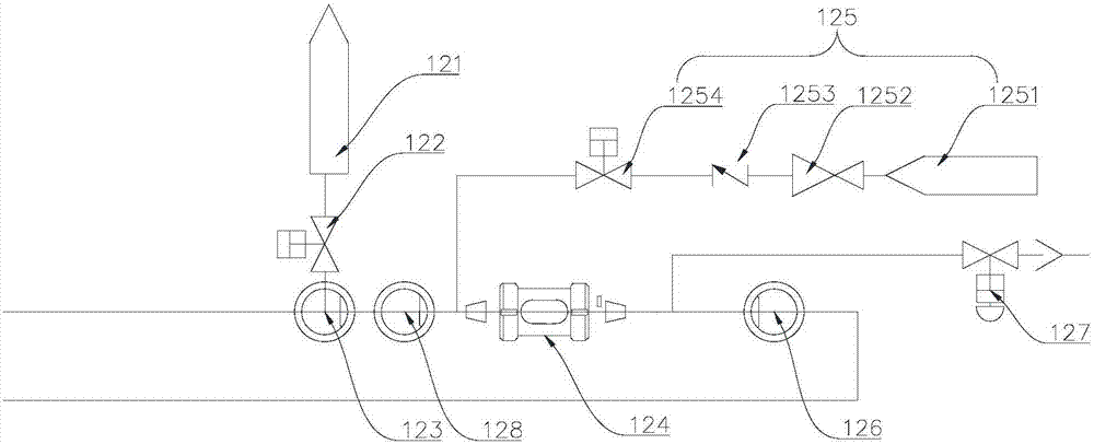
[0076] In this embodiment, there are multiple delivery pipes 210 . Preferably, there are two delivery pipes 210 . One of the delivery pipes 210 communicates with the first discharge valve 114 . The other one communicates with the second discharge valve 127 .

[0077] In this embodiment, the delivery pipe 210 is used to deliver the liquid passing through the first discharge valve 114 and the second discharge valve 127 to a predetermined position.

[0078] In summary, the present invention provides a ball ejecting system 100 and a transmission system 200. By setting the ejecting balls 1111 in the first observation window 111, the ejecting balls 1111 can transfer the ejecting balls in the ejecting ball system 100 to Connect the wine and...


PUM


Abstract

The invention provides an ejection ball system and a conveying system, and belongs to the field of chemical engineering. The ejection ball system comprises a recycle station, and an launching station,wherein the recycle station communicates with the launching station; the launching station comprises a first observation window, a first valve, a second valve, a first discharge valve and a first carbon dioxide feeding device; an ejection ball is arranged in the first observation window, so that the ejection ball separates wine from deoxidized water in the connecting pipeline in the ejection ballsystem; beer is located at one end of the ejection ball, the deoxidized water is located at the other end of the ejection ball, so that the deoxidized water and the beer are separated in the pipeline, so that the mixing of the deoxidized water and the beer can be effectively prevented in the conveying process in the pipeline, the wine loss caused by the old wine conveying mode is avoided, and the beer yield is improved; and in addition, by virtue of the carbon dioxide discharged by a first carbon dioxide feeding pipe and the deoxidized water provided by a deoxidized water feeding pipe, the working mode that only the deoxidizing water is used for wine ejection in the past is effectively changed.

Description

technical field [0001] The invention relates to the field of chemical industry, in particular to an ejector ball system and a transmission system. Background technique [0002] Existing pipes in most filling lines will have liquid residues. However, the residual liquid in the filling production line will seriously affect the whole production. Therefore, how to solve the above problems is an urgent problem to be solved at present. Contents of the invention [0003] The object of the present invention is to provide an ejector ball system and a conveying system, which can prevent the subsequent liquid in the filling production line from being polluted by residual liquid. [0004] Embodiments of the present invention are achieved like this: [0005] In a first aspect, the present invention provides a ball ejecting system, which includes a recycling station and a launching station, the recycling station communicates with the launching station, and the launching station includ...

Claims


Application Information

Patent Timeline
IPC IPC(8): B67C3/00B65B55/24B65B57/00
CPCB65B55/24B65B57/00B67C3/001B67C3/007B65B2210/06
Inventor 赵军熊节
Owner 武汉博亚德自动化工程有限公司
Why Eureka
Try Eureka