Al technical title is built by PatSnap Al team. It summarizes the technical point description of the patent document.
A reverse circulation, flow channel technology, applied in drilling equipment, earthwork drilling, drill bits, etc., can solve the problems of large inclination angle, small single crushing area, low efficiency, etc., and achieve the effect of high return speed.
Pending Publication Date: 2018-04-27
CHONGQING UNIVERSITY OF SCIENCE AND TECHNOLOGY
View PDF7 Cites 2 Cited by
Summary
Abstract
Description
Claims
Application Information
AI Technical Summary
This helps you quickly interpret patents by identifying the three key elements:
Problems solved by technology
Method used
Benefits of technology
Problems solved by technology
At present, there is no uniform industry standard for the processing and manufacturing of commonly used roller reamers, poor quality, fast wear, high consumption, generally low service life, and many in-hole accidents such as broken teeth, broken teeth, and tooth loss.
[0003] In the process of horizontal directional crossing, the conventional roller reamer has many disadvantages, such as: small single crushing area, low efficiency of slag discharge by positive circulation, welding roller, non-replaceable teeth, high cost, etc., at the same time For long-distance reaming, conventional reamers still face the problems of poor guiding ability, large swing of drill pipe and drilling tools, and large inclination angle under the action of gravity of drill tool assembly
Method used
Image
Click on the blue label to locate the original text in one second.
Reading with bidirectional positioning of images and text.
Examples
Embodiment 1
[0026] The cutting edge of the reverse circulation channel type double-stage reamer provided in the embodiment adopts a cone-PDC composite cutting structure.
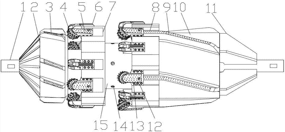
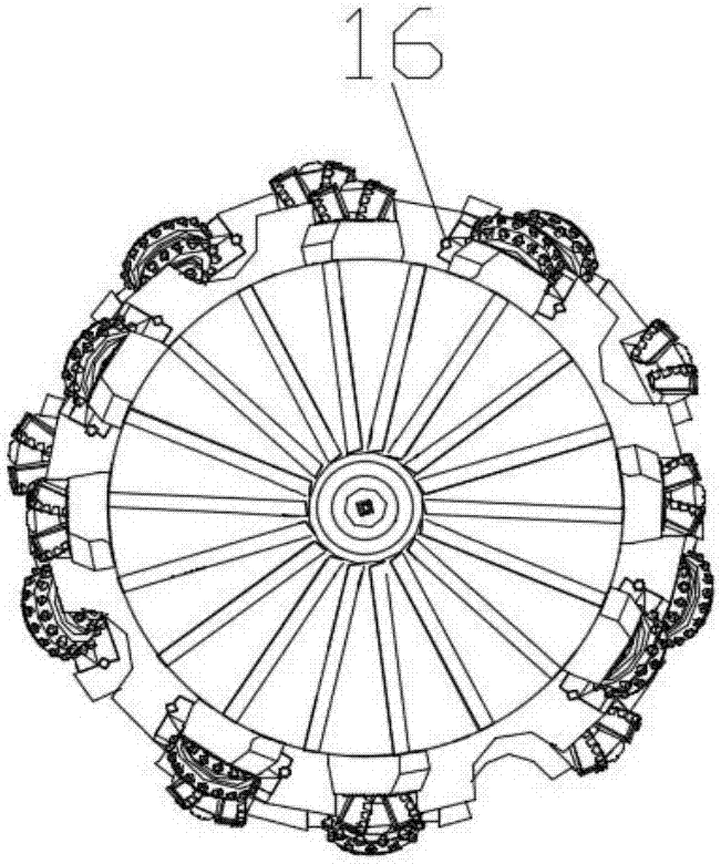
[0027] figure 1 and figure 2 The front view structure and the right view structure of the reverse circulation channel type double-stage reamer according to Embodiment 1 of the present invention are respectively shown.
[0028] Such as figure 1 and figure 2 Commonly shown, the reverse circulation channel type double-stage reamer provided by Embodiment 1 of the present invention includes: reverse circulation assembly 1, front centralizing barrel 2, front screw blade 3, cone 4, tooth palm 5, double Row of PDC (Polycrystalline DiamondCompact, polycrystalline diamond composite sheet) blade 6, primary reaming base 7, secondary reaming base 8, rear spiral blade 9, rear centralizing barrel 10, rear rib 11, limit Screw 12, fastening screw 13, slag suction pipe 14, slag suction bucket 15 and bearing pin 16; Wherein, reverse...
Embodiment 2
[0030] The cutting edge of the reverse circulation channel type double-stage compound reamer provided in the second embodiment adopts a cone-type cutting structure.
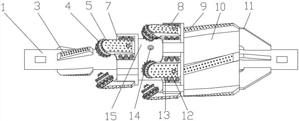
[0031] image 3 It shows the front view structure of the reverse circulation channel type double-stage reamer according to the second embodiment of the present invention.
[0032] Such as image 3 As shown, the reverse circulation channel type double-stage reamer provided by Embodiment 2 of the present invention includes: reverse circulation assembly 1, front screw blade 3, cone 4, tooth palm 5, and primary reaming base 7 , secondary reaming base 8, rear spiral blade 9, rear righting barrel 10, rear rib 11, limit screw 12, fastening screw 13, slag suction pipe 14, slag suction bucket 15 and pin 16; Wheel 4, tooth palm 5, primary reaming base 7, secondary reaming base 8, rear screw blade 9, rear righting barrel 10, rear rib 11, limit screw 12, fastening screw 13, suction The structure of the slag pipe 14, the s...
PUM
Abstract
The invention provides a reverse circulation channel-type double stage reamer comprising a reverse circulation assembly. The reverse circulation channel-type double stage reamer is characterized in that the reverse circulation assembly comprises a mandrel whose inner portion is provided with a reverse circulation structure; both ends of the mandrel are internal thread joints; a front centralizer,a first level reaming base, a second level reaming base, a rear centralizer and a slag suction bucket are welded on the shell of the mandrel; a front spiral blade is welded on the shell of the front centralizer while a rear spiral blade is welded on the shell of the rear centralizer; the slag suction bucket is welded on the shell of the mandrel and located between the first level reaming base andthe second reaming base; the slag suction bucket is communicated with the mandrel through a slag suction pipe; a reinforcing rib is respectively welded on the shell of the mandrel and the end surfaceof the rear centralizer; tooth palms and double rows of PDC (polycrystalline diamond compact) blades are respectively fixed on the first level reaming base and the second level reaming base; the end portion of the tooth palms is connected with a cone. The reverse circulation channel-type double stage reamer has the advantages of being applicable to different geology, having large cross section insingle reaming and high reaming efficiency, and achieving the effects of quick replacement of cutting edges, reducing costs and prolonging service life.
Description
technical field [0001] The invention belongs to the technical field of horizontal directional drilling, and in particular relates to a hole reaming tool suitable for crossing projects of horizontal directional drilling. Background technique [0002] Large-diameter and long-distance crossing are the key points and difficulties in the current horizontal directional drilling construction process. Roller cone reamers are commonly used for long-distance complex formation crossing. At present, there is no unified industry standard for the processing and manufacturing of commonly used cone reamers, with poor quality, fast wear, high consumption, generally low service life, and many in-hole accidents such as broken teeth, broken cones, and tooth loss. [0003] In the process of horizontal directional crossing, the conventional roller reamer has many disadvantages, such as: small single crushing area, low efficiency of slag discharge by positive circulation, welding roller, non-repl...
Claims
Application Information
Patent Timeline
Application Date:The date an application was filed.
Publication Date:The date a patent or application was officially published.
First Publication Date:The earliest publication date of a patent with the same application number.
Issue Date:Publication date of the patent grant document.
PCT Entry Date:The Entry date of PCT National Phase.
Estimated Expiry Date:The statutory expiry date of a patent right according to the Patent Law, and it is the longest term of protection that the patent right can achieve without the termination of the patent right due to other reasons(Term extension factor has been taken into account ).
Invalid Date:Actual expiry date is based on effective date or publication date of legal transaction data of invalid patent.
Patent Type & Authority Applications(China)
IPC IPC(8): E21B10/34E21B10/50E21B10/16E21B10/18
CPCE21B10/16E21B10/18E21B10/34E21B10/50
Inventor 魏秦文任斌尹永清董超群曲海任连城郭咏梅田芳巫尚蔚韩涛
Owner CHONGQING UNIVERSITY OF SCIENCE AND TECHNOLOGY