Low-power-consumption constant conduction time timing circuit design method and timing circuit

A technology with constant on-time and design methods, applied in computer-aided design, high-efficiency power electronic conversion, multiple input and output pulse circuits, etc., can solve the problems of large static power consumption of EA, difficult filtering, low light load efficiency, etc. , to achieve the effect of eliminating static power consumption, simple circuit structure and reducing power consumption

Pending Publication Date: 2018-04-27
SICHUAN ENERGY INTERNET RES INST TSINGHUA UNIV
View PDF0 Cites 1 Cited by
  • Summary
  • Abstract
  • Description
  • Claims
  • Application Information

AI Technical Summary

Problems solved by technology

The disadvantages are: 1. Low light load efficiency; 2. Limited by EA, the loop response speed is slow
The disadvantages are: 1. The output ripple is larger; 2. The EMI harmonic spectrum is too wide, and it is difficult to filter
[0008] From Equation 2, it can be obtained that the operating frequency is constant, but for low-power BUCK, figure 1 The disadvantage shown in is that the static power consumption of the EA is relatively large, which makes the need for low-power timers appear

Method used


Image

  • Low-power-consumption constant conduction time timing circuit design method and timing circuit
  • Low-power-consumption constant conduction time timing circuit design method and timing circuit
  • Low-power-consumption constant conduction time timing circuit design method and timing circuit

Examples


Embodiment Construction

[0025] In order to make the object, technical solution and advantages of the present invention clearer, the present invention will be further described in detail below in conjunction with the accompanying drawings and embodiments. It should be understood that the specific embodiments described here are only used to explain the present invention, not to limit the present invention.

[0026] Any feature disclosed in this specification (including the abstract and drawings), unless specifically stated, can be replaced by other equivalent or similar purpose alternative features. That is, unless expressly stated otherwise, each feature is one example only of a series of equivalent or similar features.

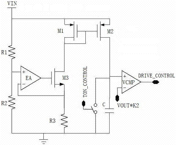
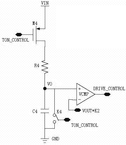
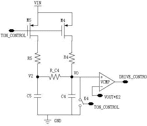
[0027] For the low power consumption constant on-time timing circuit design method, the specific method of the core idea of ​​the present invention is: use RC circuit for timing, and eliminate the static power consumption of the timer. The low-power timer uses an RC circuit for timi...


PUM


Abstract

The invention provides a low-power-consumption constant conduction time timing circuit design method and timing circuit. An RC circuit is adopted for timing and the static power consumption of the timer is eliminated. The concrete structure is that the timing circuit comprises a fourth PMOS transistor M4 of which the source electrode is connected with input voltage VIN, the gate electrode is connected with the conduction time control end TON_CONTROL and the drain electrode is connected with one end of a fourth resistor R4. The other end of the fourth resistor R4 is connected with one end of afourth capacitor C4. The other end of the fourth capacitor C4 is grounded. The input negative electrode of a comparator VCMP is connected with reference voltage, and the input positive electrode is connected between the fourth capacitor C4 and the fourth resistor R4. According to the circuit under the design method, the static power consumption of the constant conduction time timing circuit can beeliminated so that the power consumption of the whole circuit can be reduced, and the circuit structure is simple and the cost is low.

Description

technical field [0001] The invention relates to the field of electronic circuits, in particular to a design method of a low power consumption constant on-time timing circuit and a timing circuit. Background technique [0002] There are two main types of power chips on the market according to the modulation method: PWM (Pulse Width Modulation), PFM (Pulse Frequency Modulation) and PWM-PFM (Pulse Width Frequency Modulation). Both modulation methods have advantages and disadvantages: [0003] For PWM, the advantages are: 1: low noise, fixed switching frequency, easy design of EMI noise filter; 2: small ripple voltage; 3: easy control method. The disadvantages are: 1. Low light load efficiency; 2. Limited by EA, the loop response speed is slow. [0004] For PFM, there are COT, CFT and hysteresis voltage types. The advantages are: 1: high light load efficiency; 2: small static power consumption; 3: fast loop response. The disadvantages are: 1. The output ripple is larger; 2. T...

Claims


Application Information

Patent Timeline
Patent Type & Authority Applications(China)
IPC IPC(8): H02M3/158
CPCH02M3/158H02M1/0048G06F30/373G06F2119/12H03K3/355Y02B70/10G06F30/396H03K3/012H03K5/24
Inventor 李伊珂
Owner SICHUAN ENERGY INTERNET RES INST TSINGHUA UNIV
Why Eureka
Try Eureka