
Feedback control circuit

A feedback control and circuit technology, applied in the direction of control/regulation system, electrical components, adjustment of electrical variables, etc., can solve the problems of reducing product efficiency, consumption of voltage regulator tubes, and low withstand voltage value, so as to improve efficiency and reduce no-load The effect of power consumption

Pending Publication Date: 2018-04-27
MORNSUN GUANGZHOU SCI & TECH
View PDF12 Cites 0 Cited by
  • Summary
  • Abstract
  • Description
  • Claims
  • Application Information

AI Technical Summary

Problems solved by technology

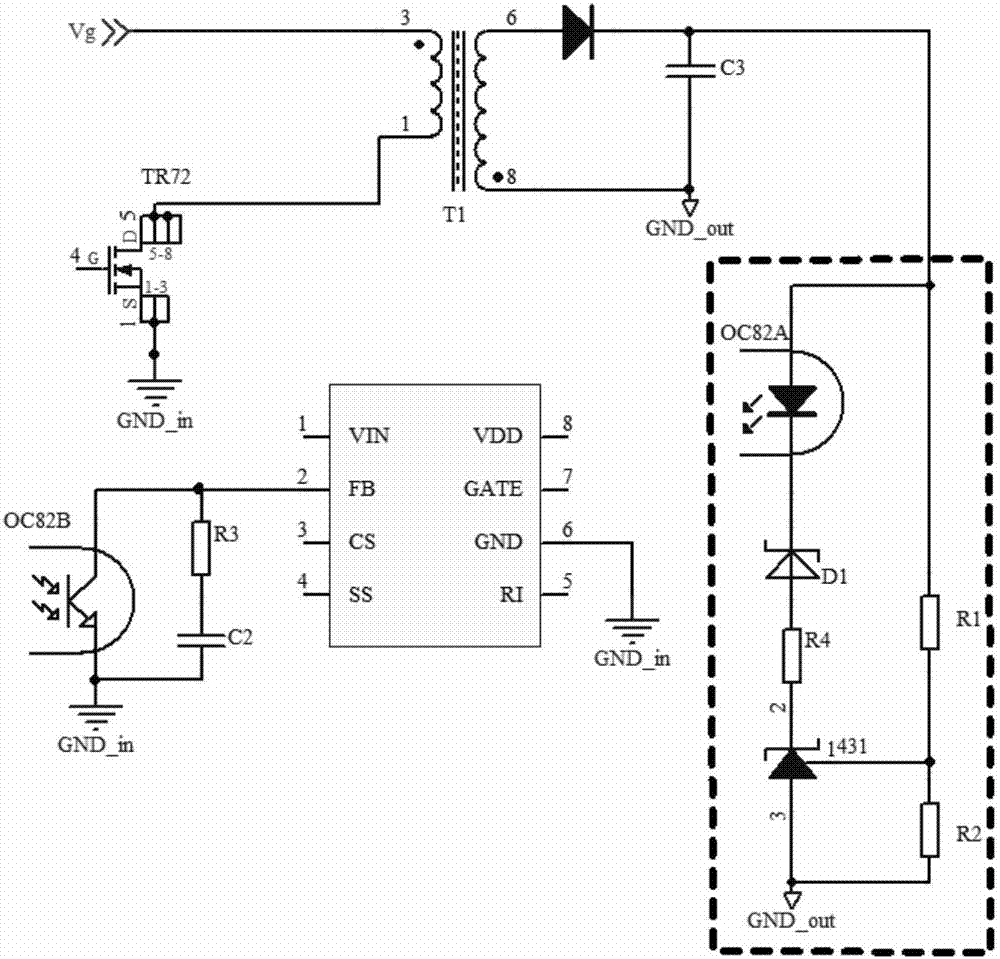
Since the voltage resistance of 431 itself is relatively low, when the output voltage exceeds 50V, most of the methods are to connect a suitable voltage regulator tube in series with the cathode of 431. The disadvantage of this method is that the voltage regulator tube is in breakdown voltage regulation for a long time. state, the failure rate will be greatly increased, and it is difficult to find a suitable voltage regulator tube. In the design process, it is necessary to use multiple voltage regulator tubes in series, which will greatly increase the failure rate of the product.
Moreover, the minimum working current of 431 is 1mA, which causes the current flowing through the Zener tube to be at least 1mA, which causes the Zener tube to consume a part of energy, so this method leads to a significant increase in the no-load power consumption of the product. Moreover, the power consumption will increase with the increase of the output voltage, especially in the high voltage output range.
And it will reduce the efficiency of the product. For low-power high-voltage output products, the shortcomings of this feedback control method are more obvious.

Method used


Image

  • Feedback control circuit
  • Feedback control circuit
  • Feedback control circuit

Examples


no. 1 example

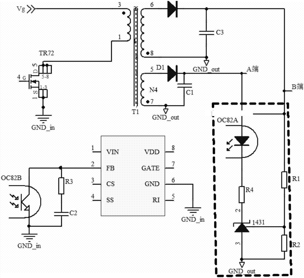
[0020] figure 2 A schematic diagram of the application of the invention is shown.

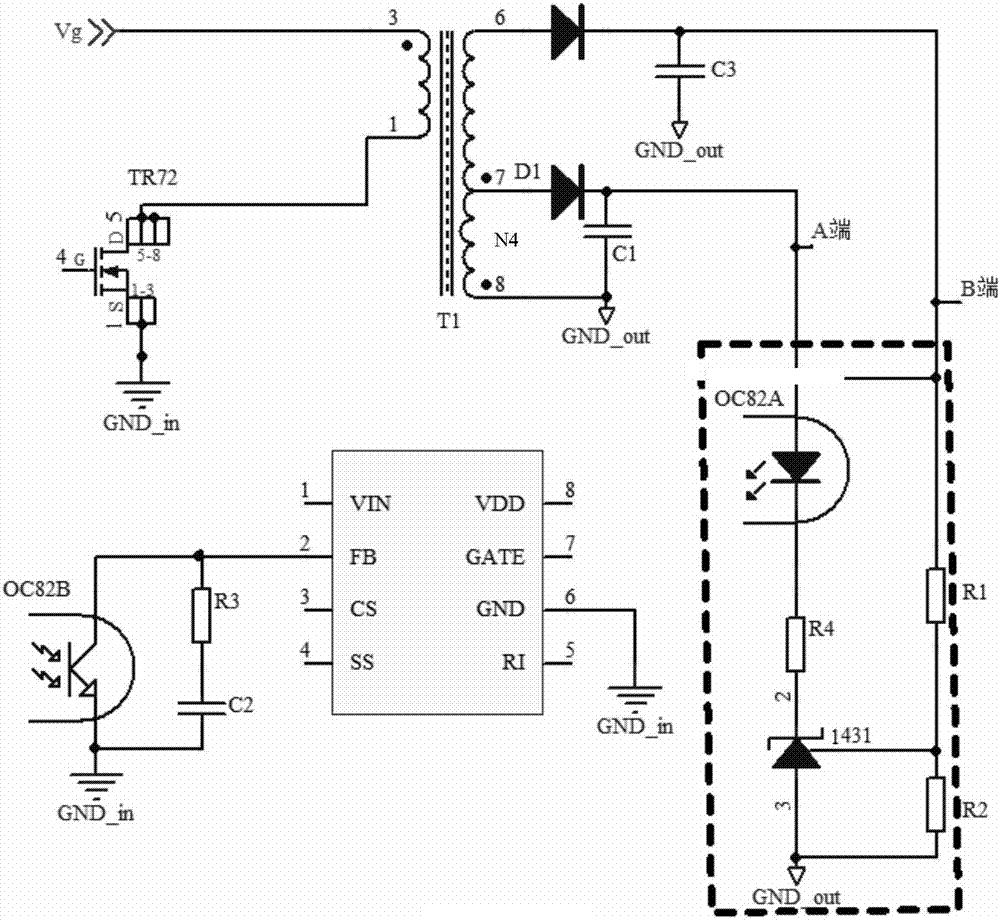
[0021] A feedback control circuit, including an output feedback winding (auxiliary winding or tapped winding), a filter circuit and a voltage stabilization feedback control unit, the voltage of the output feedback winding follows the voltage of the main power secondary winding, the two have the same polarity and share a common ground , the structure of the feedback winding can be in the form of an auxiliary winding and taking two turns from the main power winding in the form of a tap. The output terminal of the feedback winding is connected to the input terminal of the filter circuit, and a voltage V1 is generated through a filter circuit composed of diodes and capacitors. , the output terminal of the filter circuit is connected to the input terminal A of the voltage stabilization feedback control unit, the input terminal B of the feedback control unit is connected to the positive pole of the ...


PUM


Abstract

The invention provides a feedback control circuit. The circuit comprises an output feedback winding, a filter circuit and a voltage stabilization feedback control unit. A voltage of the output feedback winding follows a voltage of a secondary winding of a main power circuit, and the two voltages have a same polarity and are connected to common ground. An output terminal of the output feedback winding is connected to an input terminal of the filter circuit. Through the filter circuit, a voltage V1 is generated. An output terminal of the filter circuit is connected to an input terminal A of thevoltage stabilization feedback control unit. An input terminal B of the voltage stabilization feedback control unit is connected to an output terminal anode of the main power circuit. On one hand, theoutput terminal of the filter circuit provides an input signal to the feedback control unit; on the other hand, the output terminal of the filter circuit provides power for a chip in the feedback control unit. By using the feedback control circuit of the invention, under the condition that a voltage stabilizing diode does not need to be added to carry out voltage division when a high voltage is output, a mode of externally adding a feedback winding is adopted to realize effective and reliable voltage stabilization feedback. Design cost is saved, and more importantly, product stability is increased.

Description

technical field [0001] The invention relates to a feedback control circuit of a regulated power supply, in particular to a switching power supply which does not need to use a zener diode to divide the voltage at high voltage output. Background technique [0002] In the switching power supply, in the feedback control of the output regulated power supply, the feedback control unit of the voltage loop is mostly composed of a series connection of 431 and an isolated optocoupler. The feedback unit provides feedback signals such as figure 1 shown. Since the voltage resistance of 431 itself is relatively low, when the output voltage exceeds 50V, most of the methods are to connect a suitable voltage regulator tube in series with the cathode of 431. The disadvantage of this method is that the voltage regulator tube is in breakdown voltage regulation for a long time. In the state, the failure rate will be greatly increased, and it is difficult to find a suitable voltage regulator tu...

Claims


Application Information

Patent Timeline
IPC IPC(8): H02M3/335
CPCH02M3/33523
Inventor 许梦羊刘改冯刚
Owner MORNSUN GUANGZHOU SCI & TECH
Learn More