Self-forcing cooling high-temperature resisting mechanical sealing device

A mechanical seal device and high temperature resistant technology, which is applied in the direction of engine seal, mechanical equipment, engine components, etc., can solve the problems of mechanical seal friction pair end surface temperature rise, sealing surface leakage sealing, friction pair dry grinding, etc., to achieve enhanced heat dissipation ability, speed up medium flow rate, and prevent high temperature vaporization

Pending Publication Date: 2018-05-01
XIAN AEROSPACE PROPULSION INST
View PDF0 Cites 7 Cited by
  • Summary
  • Abstract
  • Description
  • Claims
  • Application Information

AI Technical Summary

Problems solved by technology

[0004] 1. The temperature of the end surface of the mechanical seal friction pair rises rapidly, and the friction pair appears dry grinding, thermal cracking, deformation and other phenomena
[0005] 2. The temperature of the turbine cavity is as high as 650-800°C. The existing mechanical

Method used


Image

  • Self-forcing cooling high-temperature resisting mechanical sealing device
  • Self-forcing cooling high-temperature resisting mechanical sealing device
  • Self-forcing cooling high-temperature resisting mechanical sealing device

Examples


Embodiment Construction

[0038] Below in conjunction with accompanying drawing and specific embodiment content of the present invention is described in further detail:

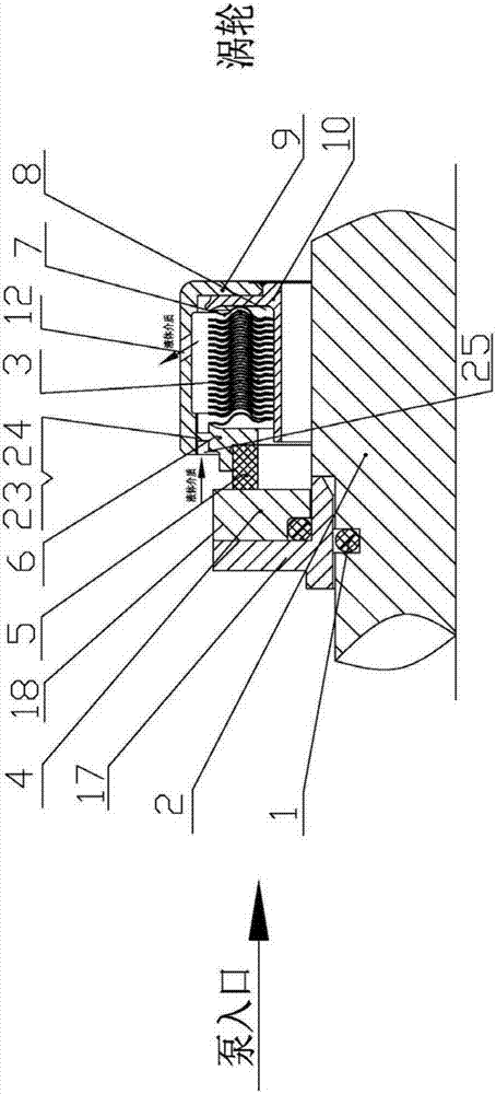
[0039] The self-forced cooling and high-temperature resistant mechanical seal device provided by the present invention is mainly arranged between the pump inlet and the turbine of the turbo pump of the liquid rocket engine. The invention can also be used in sealing devices in the fields of ships and nuclear industries, and other rotating devices that must ensure sealing, have small size and space, require multiple starts and stops, and long life.

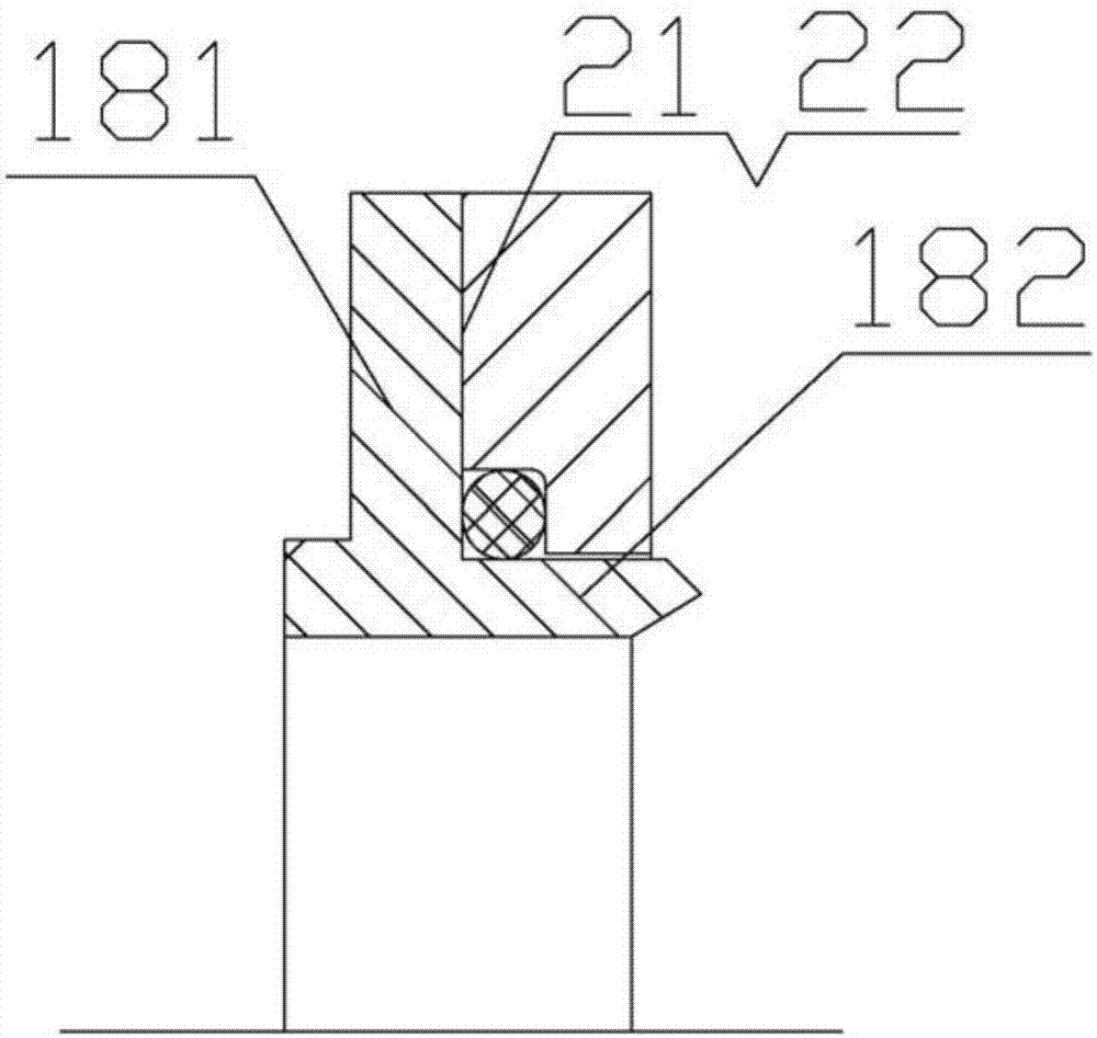
[0040] Such as Figure 1 to Figure 6 As shown, the self-forced cooling high temperature resistant mechanical seal device provided by the present invention mainly includes an O-shaped rubber ring 1, a moving ring 4, a graphite ring 5, a static ring seat 6, an annular diaphragm group 3, an annular housing 9, a heat insulation Ring 10.

[0041] The moving ring 4 is fixedly set on the end of ...


PUM


Abstract

The invention relates to a self-forcing cooling high-temperature resisting mechanical sealing device. A movable ring, a static ring seat and a heat insulation ring of the sealing device are mounted ona rotating shaft in a sleeving mode; a flow guiding groove is formed in the movable ring; an annular shell is mounted on the heat insulation ring and the static ring seat in a sleeving mode, one sideof the annular shell and the heat insulation ring are fixed and sealed, a liquid medium annular inlet is formed by the inner wall of the other side of the annular shell and the surface of the outer circle of the static ring seat, an annular membrane piece group is mounted on the heat insulation ring in a sleeving mode, a gap is formed between the annular membrane piece group and the outer ring wall of the heat insulation ring, and the outer edges of the two sides of the annular membrane piece group and the static ring seat as well as the heat insulation ring are subjected to full-length welding in the circumferential direction, so that a cavity is formed between the annular shell and the annular membrane piece group; a small hole communicating with the cavity is formed in the outer wall of the annular shell; and a cooling channel is formed by the liquid medium annular inlet, the cavity and the small hole. The problems that unstable work, leakage of a sealing face and even sealing failure of mechanical seal occur due to the fact that vaporization appears on a liquid medium are solved by arranging the flow guiding groove and the cooling channel.

Description

technical field [0001] The invention relates to the technical field of sealing, in particular to a self-forced cooling high temperature resistant mechanical sealing device. Background technique [0002] The turbopump assembly in the prior art is the core component of the liquid rocket engine propellant supply system, which mainly realizes the pressurization of the incoming medium, and delivers the propellant to the combustion chamber according to the flow and pressure required by the design, usually in the liquid rocket engine turbopump A set of mechanical sealing device is arranged on the rotating shaft between the pump inlet and the turbine, the purpose is to realize a small amount or no propellant leakage of the propellant medium into the turbine cavity. [0003] When the existing mechanical seal device works, the maximum PV value is close to 60MPa.m / s, so there will be the following problems: [0004] 1. The temperature of the end surface of the mechanical seal friction...

Claims


Application Information

Patent Timeline
IPC IPC(8): F16J15/30F16J15/18F16J15/16
CPCF16J15/30F16J15/162F16J15/18
Inventor 张峰李建克王良宋勇李正大傅春
Owner XIAN AEROSPACE PROPULSION INST
Why Eureka
Try Eureka