

Rotary hearth furnace
A technology of rotary hearth furnace and ring furnace, which is applied to furnaces, hearth furnaces, furnace types, etc., can solve the problems of low utilization rate and ineffective utilization of flue gas waste heat, so as to improve production capacity, improve reduction effect, and reduce reduction time. prolonged effect
- Summary
- Abstract
- Description
- Claims
- Application Information
AI Technical Summary
Problems solved by technology
Method used
Image

Examples
Embodiment 1
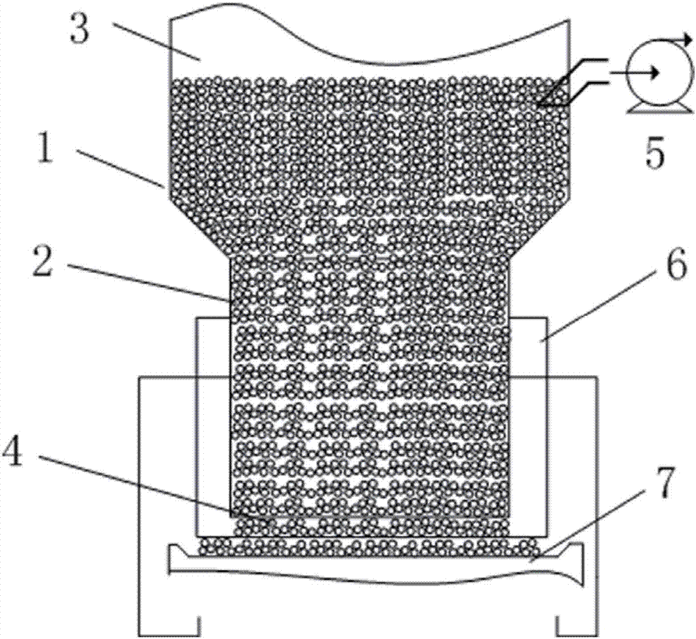
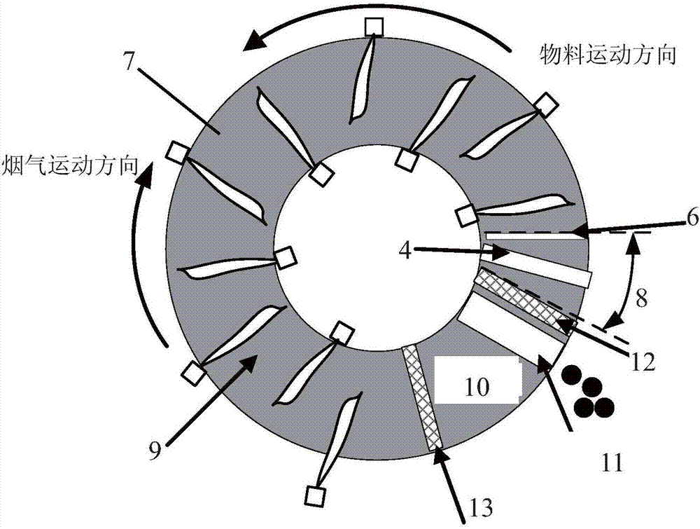
[0071] An annular hearth of a rotary hearth furnace is divided into a charging zone 8, a high-temperature reduction zone 9, a cooling zone 10 and a discharge zone, the high-temperature reduction zone 9 has an angle of 280°, the cooling zone 10 has an angle of 20°, and the charging zone 8 The sum of the angles of the discharge area and the discharge area is 60°. The charging area 8 and the discharging area are separated by a high-temperature-resistant first retaining wall 12, and the high-temperature-resistant second retaining wall 13 is used to separate the first retaining wall 12 and the second retaining wall 13 between the cooling area 10 and the high-temperature reduction area 9 The lower end is 15cm from the upper surface of the furnace bottom. The material distributing mechanism is made up of scraper plate 6 and blanking mechanism. The lower part of the feeding mechanism is a square lower material tube 2, and the upper part is a cylindrical upper material tube 1. The upp...
Embodiment 2
[0074] An annular hearth of a rotary hearth furnace is divided into a charging zone 8, a high-temperature reduction zone 9, a cooling zone 10 and a discharge zone, the high-temperature reduction zone 9 has an angle of 290°, the cooling zone 10 has an angle of 20°, and the charging zone 8 The sum of the angles of the discharge area and the discharge area is 50°. The charging area 8 is separated from the discharge area by a high-temperature resistant first retaining wall 12, and the cooling zone 10 and the high-temperature reducing area 9 are separated by a high-temperature resistant second retaining wall 13. The first retaining wall 12, the second retaining wall 13 lower ends are 5cm apart from the furnace bottom upper surface. The material distributing mechanism is made up of scraper plate 6 and blanking mechanism. The lower part of the feeding mechanism is a square lower material tube 2, and the upper part is a cylindrical upper material tube 1. The upper material tube 1 and...
Embodiment 3
[0077] An annular hearth of a rotary hearth furnace is divided into a charging zone 8, a high-temperature reduction zone 9, a cooling zone 10 and a discharge zone, the high-temperature reduction zone 9 has an angle of 270°, the cooling zone 10 has an angle of 30°, and the charging zone 8 The sum of the angles of the discharge area and the discharge area is 60°. The charging area 8 is separated from the discharge area by a high-temperature resistant first retaining wall 12, and the cooling zone 10 and the high-temperature reducing area 9 are separated by a high-temperature resistant second retaining wall 13. The first retaining wall 12, the second retaining wall 13 lower ends are 5cm apart from the furnace bottom upper surface. The material distributing mechanism is made up of scraper plate 6 and blanking mechanism. The lower part of the feeding mechanism is a square lower material tube 2, and the upper part is a cylindrical upper material tube 1. The upper material tube 1 and...
PUM
| Property | Measurement | Unit |
|---|---|---|
| angle | aaaaa | aaaaa |
Abstract
Description
Claims
Application Information