
NMF-based micro-seismic weak signal recognition method

A recognition method and weak signal technology, applied in the field of signal processing, can solve the problems of limited resolution, no localization ability in time domain, frequency aliasing end effect, etc., and achieve the effect of accurate classification results, comprehensive feature set, convenient real-time performance, etc.

Active Publication Date: 2018-05-04
GUILIN UNIV OF ELECTRONIC TECH
View PDF6 Cites 14 Cited by
  • Summary
  • Abstract
  • Description
  • Claims
  • Application Information

AI Technical Summary

Problems solved by technology

Among them, the short-time Fourier transform (STFT) was proposed by Gabor in 1946. It has good localization ability in the frequency domain, but it has no localization ability in the time domain, and it is difficult to find time-varying non-stationary signals. A suitable time window to accommodate different time periods
In the 1980s, Y. Meyer et al. introduced the continuous wavelet transform (CWT) to make up for the shortcomings of the fast Fourier transform. It has good localization capabilities in both the time domain and the frequency domain, but in the same project The problem uses different wavelet functions and the analysis results are very different
In 1996, Stockwell proposed that the S-transform (ST) integrates the advantages of the short-time Fourier transform (STFT) and the continuous wavelet transform (CWT), but it is limited by the Heisenberg uncertainty principle.
[0004] In 1998, Huang proposed Empirical Mode Decomposition (EMD) decomposition. In 2012, Cheng Junsheng proposed the Local Feature Scale Decomposition (LCD) method on the basis of Huang to improve the efficiency of EMD decomposition, but both of them extracted a series of different Intrinsic mode components (IMF) with characteristic time scales have frequency confusion and endpoint effects, and it is difficult to comprehensively extract the characteristic information of microseismic signals

Method used


Image

  • NMF-based micro-seismic weak signal recognition method
  • NMF-based micro-seismic weak signal recognition method
  • NMF-based micro-seismic weak signal recognition method

Examples


Embodiment

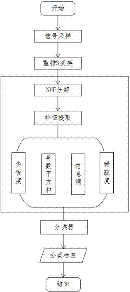
[0056] A method for distinguishing weak signals of microseisms based on NMF, the flow chart is as follows figure 1 As shown, it specifically includes the following steps:

[0057] (1) The microseismic data collected in a coal mine is x=x 1 ,x 2 ,...,x n T .

[0058] (2) Sampling the collected data at equal intervals plotted with matlab such as figure 2 Its waveform diagram is shown.

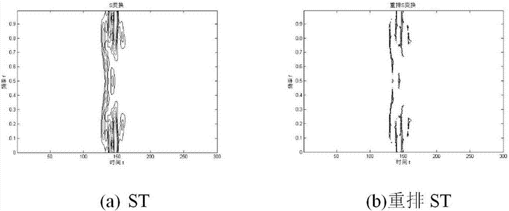
[0059] (3) Perform rearrangement S transformation on the signal x(n).

[0060] (4) If the column of x is greater than the row, go to step (5), otherwise go to step (6).

[0061] (5) Transpose x and assign it to A itself x=x T ; Guarantee that x is a column vector.

[0062] (6) If the number of input parameters is 1, go to step (7), otherwise go to step (8).

[0063] (7) Let the minimum sampling frequency be f min =0, the maximum sampling frequency f max =f Nyquist , the sampling interval T=1.

[0064] (8) Display parameters: minimum sampling frequency f min , the maximum samplin...


PUM


Abstract

The invention discloses an NMF-based micro-seismic weak signal recognition method. The method comprises the following steps of: firstly carrying out time frequency analysis on micro-seismic signals byadoption of S transformation, and rearranging time frequency spectrums in a frequency direction; factorizing a rearranged time frequency matrix by adoption of non-negative matrix factorization (NMF)so as to obtain a frequency domain base vector and a time domain position vector; extracting characteristic parameters such as sharpness, derivative quadratic sum, information entropy and sparseness to construct characteristic spaces of the micro-seismic signals; and finally classifying the micro-seismic signals by adoption of a least squares support vector machine (LSSVM). The method is capable of strengthening low-frequency weak signals and improving the time frequency resolution ratios, and has good time domain and frequency domain localization abilities.

Description

technical field [0001] The invention relates to the technical field of signal processing, in particular to an NMF-based microseismic weak signal identification method. Background technique [0002] The monitoring of microseismic signals is of great significance to the safe production of coal mines. The earlier the early warning of coal mine collapse, the smaller the chance of accidents. The initial coal mine collapse will be accompanied by a series of weak rock crack signals, but these weak rock crack signals are easily overwhelmed by mechanical noise, so finding a way to extract the weak signal features is the key to ensuring safe production in coal mines . Microseismic signals are typical non-linear and low signal-to-noise ratio signals, which include rock fracture microseismic signals (hereinafter referred to as microseismic signals), coal mine blasting microseismic signals (hereinafter referred to as blasting signals), mechanical vibrations and other construction noise...

Claims


Application Information

Patent Timeline
IPC IPC(8): G06K9/00G06K9/62G01V1/28
CPCG01V1/288G06F2218/08G06F2218/12G06F18/2411G06F18/214
Inventor 张法全王海飞肖海林毛学港王国富叶金才王小红贾小波
Owner GUILIN UNIV OF ELECTRONIC TECH
Learn More