
Vertical conveying machine for cells, vertical cell film coating machine, and film coating method of vertical cell film coating machine

A conveyor and coating machine technology, applied in the direction of conveyors, conveyor objects, transportation and packaging, etc., can solve the problems affecting the thickness of the cell, the deviation between the position of the cell and the position of the protective film of the cell, and the influence of the cell process. , to simplify the structure of the equipment and the operation process, ensure the consistency of the position, and improve the efficiency of the coating.

Active Publication Date: 2018-05-08
HEFEI JUYI POWER SYST CO LTD
View PDF8 Cites 3 Cited by
  • Summary
  • Abstract
  • Description
  • Claims
  • Application Information

AI Technical Summary

Problems solved by technology

[0006] The existing battery automatic coating equipment basically needs to transport the battery cells through the conveyor line. The existing conveyor lines, such as belt conveyor lines, often need to be combined with sensors or by controlling the number of rotations of the motor to determine the battery life. Whether the core is transported to the feeding position increases the complexity of the control circuit of the equipment made by the sensor and makes the control difficult; at the same time, due to the signal transmission process, there is often a certain delay in the stop of the transmission line, which causes There is a certain error between the actual loading position of the battery cell and the optimal target position, resulting in a certain deviation between the position of the battery cell and the position of the cell protective film during the subsequent coating, which affects the accuracy of the subsequent coating operation and affects the final coating. adverse effect on quality
[0007] Moreover, when manually placing the battery cells on the transmission line, the distance between the battery cells on the transmission line cannot be accurately controlled. If the sensor is not used to control the start and stop of the motor, the subsequent battery cells cannot be accurately transported. to the target loading position
[0008] In addition, most of the existing coating equipment has air bubbles on the surface of the coated cell, which affects the thickness of the cell and affects the subsequent cell process, and the cost of the equipment is high, and the efficiency cannot meet the output.
[0009] Furthermore, when the existing coating equipment performs cell coating, it is often necessary to keep the cell in a flat state (that is, to use the large side of the cell as the supporting surface) to facilitate the transportation during the coating process, and the cell It is often necessary to be in a vertical state on the conveyor line of loading and unloading, which causes the battery cell to be switched between the vertical state and the lying state during the automatic coating process, which not only makes the processing steps more cumbersome, and thus It also causes the automatic coating equipment to need a corresponding switching structure, and the overall structure of the equipment is more complicated. At the same time, the stable clamping of the horizontal battery cell is also more difficult than the vertical battery cell.

Method used


Image

  • Vertical conveying machine for cells, vertical cell film coating machine, and film coating method of vertical cell film coating machine
  • Vertical conveying machine for cells, vertical cell film coating machine, and film coating method of vertical cell film coating machine
  • Vertical conveying machine for cells, vertical cell film coating machine, and film coating method of vertical cell film coating machine

Examples


Embodiment Construction

[0056] Objects, advantages and features of the present invention will be illustrated and explained by the following non-limiting description of preferred embodiments. These embodiments are only typical examples of applying the technical solutions of the present invention, and all technical solutions formed by adopting equivalent replacements or equivalent transformations fall within the protection scope of the present invention.

[0057] In the description of the scheme, it should be noted that the terms "center", "upper", "lower", "left", "right", "front", "rear", "vertical", "horizontal", " The orientation or positional relationship indicated by "inner", "outer", etc. is based on the orientation or positional relationship shown in the drawings, and is only for the convenience of description and simplification of description, rather than indicating or implying that the device or element referred to must have a specific orientation , constructed and operated in a particular or...


PUM


Abstract

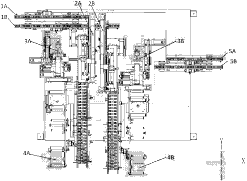
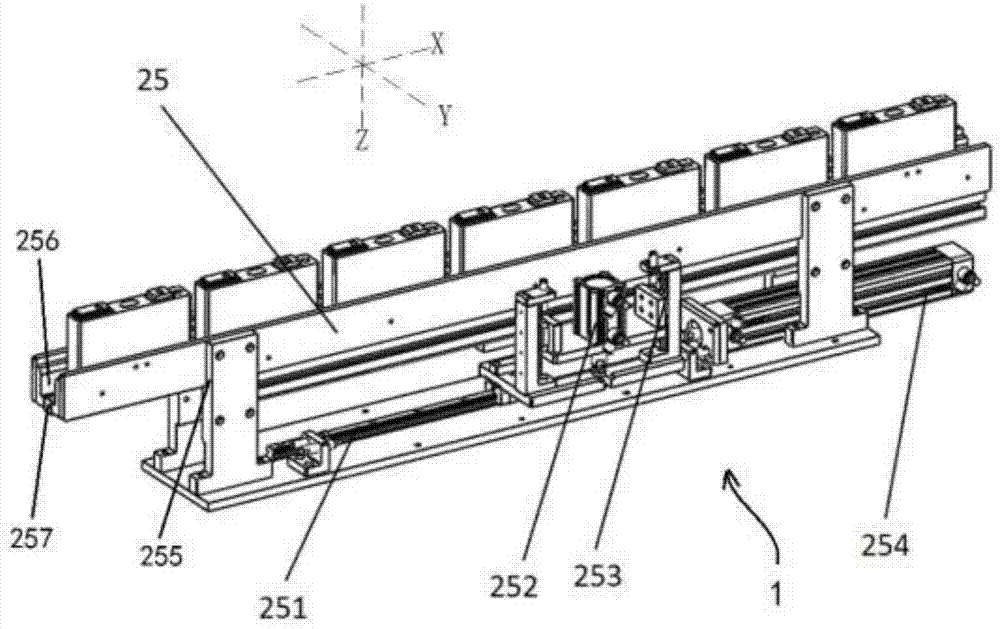
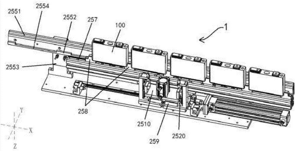
The invention discloses a vertical conveying machine for cells, a vertical cell film coating machine, and a film coating method of the vertical cell film coating machine. The vertical conveying machine comprises two brackets, and further comprises a lifting and forward moving device, wherein the brackets are symmetrically arranged in a spacing manner; main rods of the brackets extend along the first axis direction and are matched to form a supporting groove used for the placement of cells; and the lifting and forward moving device is used for driving all the cells in the supporting groove to rise synchronously, move forward by a certain distance after the cells are separated from the bottom of the supporting groove, and then fall back to the bottom of the supporting groove. The vertical conveying machine disclosed by the invention has the advantages that through the supporting groove, the cells can remain vertical and can be prevented from toppling; an air cylinder is adopted for the conveying of the cells, the start-stop control based on the combination with a sensor is not needed, and the circuit structure is simplified; meanwhile, the vertical conveying machine is prevented frombeing influenced by the delay of a control signal, so that the cells can be correctly moved to a target position, the influence of a cell position error on the follow-up machining precision can be avoided, and the machining precision can be guaranteed; and furthermore, the position consistency of all to-be-machined cells can be guaranteed, and then the final film coating quality consistency can be guaranteed.

Description

technical field [0001] The invention relates to the field of logistics sorting, in particular to a cell vertical conveyor, a vertical cell coating machine and a coating method thereof. Background technique [0002] The new energy industry has become the mainstream development trend of automobile manufacturers. With the strong support of the state, the new energy industry is becoming an emerging industry with broad market prospects. [0003] Lithium batteries are the core components of new energy vehicles, and the market demand is increasing day by day. As live products, batteries are used in the automotive industry with extremely high safety requirements. Ensuring foolproof safety is the primary consideration. [0004] Adhesive tape (cell protective film) is widely used by lithium battery manufacturers as the insulating medium for cell protection, but the manual coating of the battery greatly limits the production efficiency of the battery, and the man-made uncontrollable fa...

Claims


Application Information

Patent Timeline
Patent Type & Authority Applications(China)
IPC IPC(8): B65G23/26B65G47/90H01M10/058
CPCH01M10/058B65G23/26B65G47/90Y02E60/10Y02P70/50
Inventor 张正初韩志荣靳贺凯郑冬冬
Owner HEFEI JUYI POWER SYST CO LTD
Learn More