Capacitor lead wire connecting structure and manufacturing method thereof

A connection structure and manufacturing method technology, which is applied in the field of capacitors, can solve the problems that the copper tube cannot be completely attached to the copper stranded wire, the resistance at the joint is large, and the copper stranded wire is loose, so as to reduce inspection time, reduce heat generation, and secure high performance and reliability

Pending Publication Date: 2018-05-08
WUXI SUNKING POWER CAPACITOR CO LTD
View PDF7 Cites 0 Cited by
  • Summary
  • Abstract
  • Description
  • Claims
  • Application Information

AI Technical Summary

Problems solved by technology

Manual crimping has the risk of copper stranded wire loosening or even pressure leakage due to poor crimping;
[0005] 2. The crimped copper tube cannot fully fit the copper stranded wire, and the resistance at the connection is relatively large
[0006] 3. There are many working steps, which can only be completed after 2 to 3 operations.

Method used


Image

  • Capacitor lead wire connecting structure and manufacturing method thereof

Examples


Embodiment Construction

[0028] The present invention will be further described below in conjunction with the accompanying drawings and embodiments.

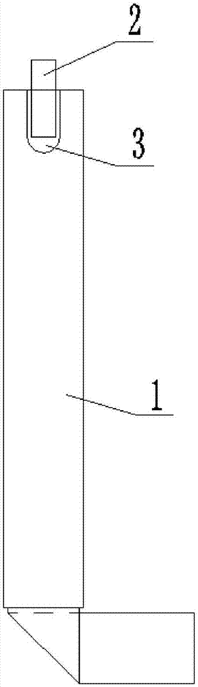
[0029] Such as figure 1 The connection structure of the lead-out wires of capacitors shown includes a core lead-out connecting piece 1 and a copper stranded wire 2, the end face of the core lead-out connecting piece 1 is provided with a fixing groove 3, and the copper stranded wire 2 is arranged in the fixing groove 3 Inside; the depth of the fixing groove 3 is 15-25mm; the aperture of the fixing groove 3 is equal to the diameter of the copper strand 2; the copper strand 2 is set in the fixing groove 3 by welding.

[0030] A method for making a connection structure of capacitor lead wires, comprising the following steps:

[0031] Step 1, using a mold to stamp the fixing groove 3 at one end of the connecting piece 1 leading out of the core;

[0032] The size of the fixing groove 3 is moderate and reasonable, and it needs to be matched with the size of ...


PUM


Abstract

The invention relates to a capacitor lead wire connecting structure and a manufacturing method thereof. The capacitor lead wire connecting structure comprises a core lead-out connecting piece and a copper stranded wire. The end face of the core lead-out connecting piece is provided with a fixing groove. The copper stranded wire is arranged inside the fixing groove. The manufacturing method comprises the following steps: 1, punching the fixing groove at one end of the core lead-out connecting piece by using a mold; 2, placing the capacitor bushing copper stranded wire into the fixing groove atone end of the core lead-out connecting piece; 3, melting a tin bar into tin water by using electric soldering iron, causing the tin water to slowly penetrates gaps between the copper stranded wire and the fixing groove, repeating the soldering three times until the tin water completely fills the fixing groove, and covering the copper stranded wire with three tin layers; and 4, removing the residual tin with the high-temperature electric soldering iron. The capacitor lead wire connecting structure completely avoids the influences of manmade omitted pressing and virtual pressing, improves connection reliability, greatly reduces the contact resistance at the joint, and can withstand high-strength and high-current impulse discharge.

Description

technical field [0001] The invention relates to the field of capacitors, in particular to a connection structure between a copper stranded wire drawn out from a capacitor casing and a leaded wire of a core body. Background technique [0002] Since the terminals of high-voltage power capacitors are drawn out by bushings, many manufacturers currently use direct cold crimping to connect the lead-out wires of the bushings to the core leads. The wire pliers press a 40mm long copper tube on the other end of the copper stranded wire, and the other end of the copper tube crimps the copper stranded wire of the capacitor bushing. [0003] The following problems often arise during the production process: [0004] 1. The copper stranded wire of the bushing and the copper stranded wire welded on the lead-out connecting piece of the core are connected through the transition connection of the copper tube, which needs to be crimped twice on the copper tube. Manual crimping has the risk of...

Claims


Application Information

Patent Timeline
Patent Type & Authority Applications(China)
IPC IPC(8): H01G13/00H01G2/00
CPCH01G2/00H01G13/00
Inventor 孟亚运梁晓韩旭陈聪葛昌晶
Owner WUXI SUNKING POWER CAPACITOR CO LTD
Why Eureka
Try Eureka