Ultrasonic emulsion breaking oil-gas-water separator and separation method

An oil-gas-water separator technology, applied in the field of oil exploitation, can solve the problems of not using upper oil enrichment and lower water enrichment, destroying oil-water-gas separation, weak demulsification function, etc., to ensure long-term stable operation effect and on-site adaptation. The effect of strong performance and elimination of the effect of system scaling

Active Publication Date: 2018-05-11
上海兴全电力技术有限公司
View PDF2 Cites 2 Cited by
  • Summary
  • Abstract
  • Description
  • Claims
  • Application Information

AI Technical Summary

Problems solved by technology

However, judging from the drawings of the patent, the multi-layer sloping plate inside the water phase outlet pipe is closely connected with the pipe. This structure completely isolates the pipe into multiple small spaces, and does not use the enrichment of the upper oil and the lower water. In addition, the inclined plate sedimentation technology only increases the "horizontal projected area of ​​the flow channel" in the unit volume, and the demulsification function of the emulsion of crude oil is very weak, and it is only effective for larger oil droplets and water droplets. The separation effect is good; more importantly, the implementation of this patented technology cannot avoid the problem of scaling. Scaling is a common problem in oilfield gathering and transportation pipelines, especially in the current tertiary oil recovery stage. The scaling problem is more serious. Although the plate increases the separation effect of oil, water and gas, it also increases the chance of scaling. Scaling on the inclined plate destroys the running channels of oil droplets and water droplets, affecting the separation effect. Gas separation, and will cause production downtime accidents

Method used


Image

  • Ultrasonic emulsion breaking oil-gas-water separator and separation method
  • Ultrasonic emulsion breaking oil-gas-water separator and separation method
  • Ultrasonic emulsion breaking oil-gas-water separator and separation method

Examples


Embodiment Construction

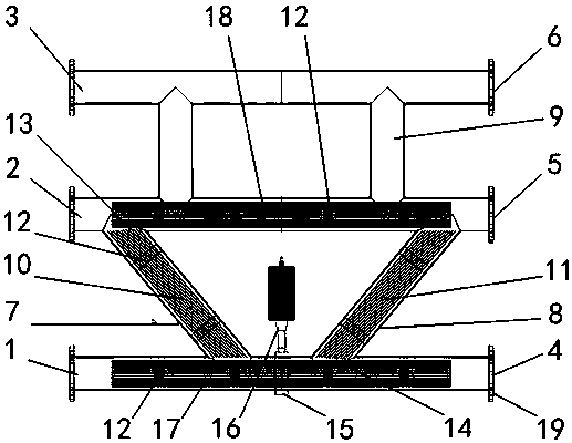
[0035] Such as figure 1 and Figure 5 Shown, the present invention has multiple in actual operation figure 1 The shown oil-water-gas separation module consists of Figure 5For the oil-water-gas separation unit shown, the specific number of components is mainly determined by the characteristics of the incoming crude oil on site, and the equipment of other oil-water separation equipment on site is also considered. In short, the more oil-water-gas separation modules in the oil-water-gas separation unit, the more The better the separation.

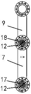
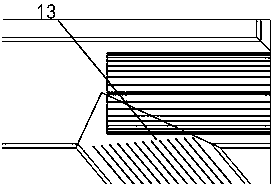
[0036] Such as Figure 1-3 As shown, the present invention discloses an ultrasonic demulsification oil-gas-water separator, comprising a liquid inlet pipe 1, an oil phase pipe 2, a gas phase pipe 3 parallel to each other, a slant plate support rod 12 and an ultrasonic vibration transmission ring 15. The liquid pipe 1 is connected to the oil phase pipe 2 arranged above it at an angle of 40° to 50° through the first inclined standpipe 7 and ...


PUM


Abstract

The invention relates to an ultrasonic emulsion breaking oil-gas-water separator and a separation method. The main structure of the ultrasonic emulsion breaking oil-gas-water separator comprises a liquid inlet pipe, an oil phase pipe, a gas phase pipe, a first inclined stand pipe, a second inclined stand pipe, gas collecting pipes and an ultrasonic transducer, wherein a liquid inlet pipe sloping plate bundle and an oil phase pipe sloping plate bundle are arranged in the liquid inlet pipe and the oil phase pipe respectively; a plurality of sloping plate support rods are arranged on the plate bundles and tightly connected with the inner walls of the pipes; the first inclined stand pipe and the second inclined stand pipe are arranged between the liquid inlet pipe and the oil phase pipe; the gas collecting pipes are arranged between the oil phase pipe and the gas phase pipe. According to the ultrasonic emulsion breaking oil-gas-water separator and the separation method, multi-stage oil-gas-water separating and descaling effects can be achieved, the problem of complex emulsification can be solved, production efficiency of the oil-gas-water separation is remarkably improved, time is shortened, petroleum crude oil quality is improved, petroleum crude oil loss is reduced, demulsification efficiency of a demulsifier is increased, use quantity of the demulsifier is reduced, and the requirement for the environment is reduced.

Description

technical field [0001] The invention belongs to the technical field of petroleum exploitation, and in particular relates to an ultrasonic demulsification oil-gas-water separator and a separation method. Background technique [0002] As many oilfields in my country enter secondary and tertiary oil recovery, the quality of crude oil deteriorates, and the chemical composition and oil-water emulsion structure become more complex. Most of the crude oil produced in oilfields exists in the form of emulsion, and the dispersion structure of emulsion is very complicated. There are oil-in-water (O / W), water-in-oil (W / O), water-in-oil and oil-in-oil (O / W / O), oil-in-water and water-in-water (W / O / W), two Secondary oil recovery is mainly water-in-oil type (W / O), and tertiary oil recovery is mainly oil-in-water type (O / W). Salt impurities and moisture in crude oil will seriously affect the processing and production process of crude oil, increase transportation costs, increase energy consumpt...

Claims


Application Information

Patent Timeline
Patent Type & Authority Applications(China)
IPC IPC(8): C10G53/02
CPCC10G53/02
Inventor 褚兴全褚校崧白文路
Owner 上海兴全电力技术有限公司
Why Eureka
Try Eureka