Capacitor voltage conversion circuit

A technology for converting circuits and capacitor voltages, which is applied in the directions of capacitance measurement, resistance/reactance/impedance measurement, and electrical variable measurement, which can solve problems such as large errors, low detection sensitivity, and limited scope of application.

Active Publication Date: 2018-05-11
四川泛华航空仪表电器有限公司
View PDF10 Cites 2 Cited by
  • Summary
  • Abstract
  • Description
  • Claims
  • Application Information

AI Technical Summary

Problems solved by technology

[0004] In order to solve the capacitance-to-voltage conversion method in the prior art, there are technical problems such as complex stru

Method used


Image

  • Capacitor voltage conversion circuit
  • Capacitor voltage conversion circuit
  • Capacitor voltage conversion circuit

Examples


Embodiment 1

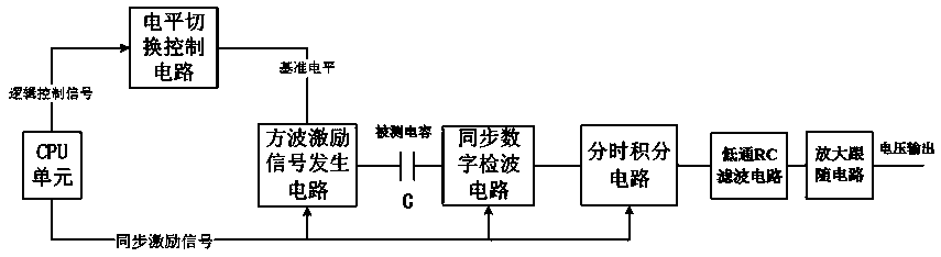
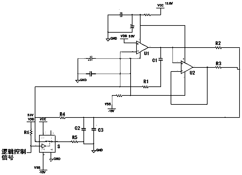
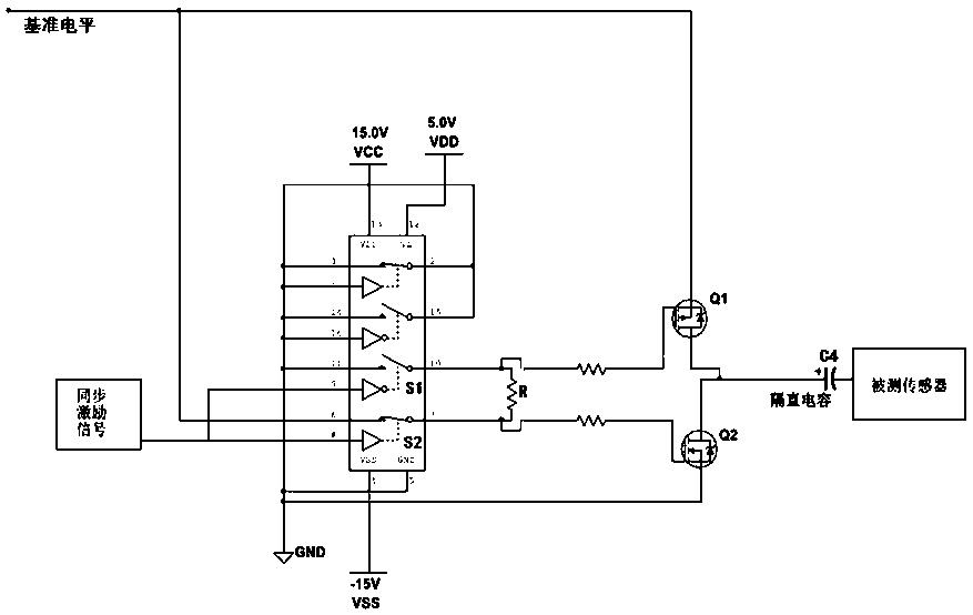
[0027] Such as figure 1 As shown, a capacitance-voltage conversion circuit described in this embodiment includes a CPU unit, a square wave excitation signal generating circuit, and a measured capacitance C, and is characterized in that: it also includes a synchronous digital detection circuit, a time-sharing integration circuit, a low-pass RC filter circuit; the CPU unit is used to generate a synchronous excitation signal and a logic control signal, and the synchronous excitation signal is a logic digital signal whose "0" level and "1" level alternate by a fixed period; the square wave excitation The signal generation circuit is used to convert a reference level into a square wave excitation signal output by using the synchronous excitation signal as a trigger signal, and the square wave excitation signal is an analog signal with driving capability for applying to the measured capacitor C Encourage the measured capacitor C; the synchronous digital detection circuit is connecte...

Embodiment 2

[0029] On the basis of above-mentioned embodiment, propose embodiment 2, as figure 1 As shown, it is characterized in that: the capacitor voltage conversion circuit also includes a level switching control circuit; the level switching control circuit is used to be controlled by the logic control signal output by the CPU unit, to provide 5V or 5V for the square wave excitation signal generating circuit 10V reference level.

Embodiment 3

[0031] On the basis of above-mentioned embodiment, propose embodiment 3, as figure 1 As shown, it is characterized in that: the capacitive voltage conversion circuit also includes an amplification follower circuit, and the amplification follower circuit is used to amplify the DC level after the low-pass RC filter circuit.


PUM


Abstract

The present invention provides a capacitor voltage conversion circuit. The capacitor voltage conversion circuit comprises CPU unit, a square-wave excitation signal generation circuit, a detected capacitor (C), a synchronous digital detecting circuit, a time-sharing integrating circuit and a low-pass RC filter circuit. The CPU unit is configured to generate synchronous excitation signals and logiccontrol signals; the square-wave excitation signal generation circuit is configured to take the synchronous excitation signals as triggering signals to convert a reference level as square-wave excitation signal output configured to be applied to the detected capacitor (C) to excite the detected capacitor (C); the synchronous digital detecting circuit is connected with a returning end of the detected capacitor (C) to take the synchronous excitation signals as triggering signals to detect returning signals of the detected capacitor (C) to integration half-wave signals; and the time-sharing integrating circuit is configured to take the synchronous excitation signals as triggering signals to perform time sharing integration of the integration half-wave signals to output a direct current level.The capacitor voltage conversion circuit solves the technical problems that the capacitor voltage conversion circuit is complex in structure, limited in application range, large in error and low in detection sensitivity.

Description

technical field [0001] The invention relates to the technical field of capacitance measurement. In particular, it relates to a capacitive voltage conversion circuit. Background technique [0002] At present, capacitive sensors are widely used because of their simple structure, good dynamic response, high sensitivity, and ability to work in harsh environments. The basic principle of the capacitive sensor is to reflect the change of the measured physical quantity by measuring the transformation of capacitance. The capacitance of a capacitive sensor is usually small, and its measurement method is mainly to convert the capacitance into a corresponding voltage, and then digitally convert the voltage signal through analog-to-digital conversion before collecting and analyzing it. Among the current capacitance-to-voltage conversion methods: LRC bridge measurement method has a complex structure and requires many hardware resources, so the cost is high, and the measurement result is...

Claims


Application Information

Patent Timeline
IPC IPC(8): G01R27/26G01D5/24
CPCG01D5/24G01R27/2605
Inventor 张思宇樊伟李霞师显强
Owner 四川泛华航空仪表电器有限公司
Why Eureka
Try Eureka