Bus synchronous control framework and control method

A technology of synchronous control and control method, which is applied to the photolithography process of the pattern surface, the photolithography process exposure device, optics, etc., which can solve the problem of the strict requirements of the maglev dual-stage photolithography machine, and achieve increased bandwidth and enhanced stability. , The effect of reducing the number of pins occupied

Active Publication Date: 2018-05-11
SHANGHAI MICRO ELECTRONICS EQUIP (GRP) CO LTD
View PDF4 Cites 6 Cited by
  • Summary
  • Abstract
  • Description
  • Claims
  • Application Information

AI Technical Summary

Problems solved by technology

[0004] The maglev dual-stage lithography machine has very strict requirements on the control system. It is required to ensure the accuracy of the control while ensuring the data transmission bandwidth. This is a big challenge for the data transmission bus and the hardware processor.

Method used


Image

  • Bus synchronous control framework and control method
  • Bus synchronous control framework and control method
  • Bus synchronous control framework and control method

Examples


Embodiment 1

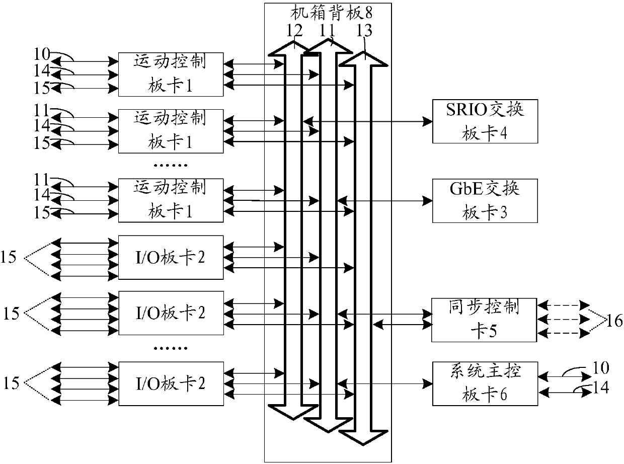
[0045] Such as figure 1 As shown, the present invention is based on a synchronous control framework of SRIO (Serial RapidIO) bus, including motion control board 1, I / O board 2, GbE (Gigabit Ethernet) switching board 3, SRIO switching board 4 , synchronous control board 5 and system main control board 6. Among them, there are multiple motion control boards 1 and I / O boards 2 respectively.

[0046] The system main control board 6 receives commands from the host computer 7 and initializes the entire system; specifically, the system main control board 6 receives commands issued by the host computer 7 through the GbE control bus 11 on the chassis backplane 8 , including initialization, machine parameter delivery, distribution of motion control board 1 operating firmware, etc. After the system main control board 6 interprets the command, it sends the command to each of the system through the GbE control bus 11 on the chassis backplane 8 Boards, including motion control board 1, I / ...

Embodiment 2

[0066] Such as Image 6 As shown, the difference from Embodiment 1 is that in this embodiment, the synchronous switching board 9 replaces the synchronous control board 5, and there is no GbE switching board 3 and SRIO switching board 4 in the synchronous control framework, which simplifies the control Architecture, when there is no redundant synchronous bus 13 on the chassis backplane 8, the synchronous control board 5 provides the system clock for the synchronous system, the clock bus is connected to the timing / counter in each board, and the timing / counter in the board The counter performs clock timing. When the set value is reached, an interrupt signal is generated and broadcast to the CPU of each board to start a new servo cycle.

[0067] Sometimes in order to save hardware resources and increase the realizability of the system, the servo interrupt information and system synchronization status information are directly transmitted through the SRIO data bus 12: the system agr...


PUM


Abstract

The present invention discloses a bus synchronization control framework and control method. The bus synchronization control framework includes a system main control board card which receives a commandof an upper computer, and initializes the whole system; a synchronization control board card which receives servo interruption information and a system synchronization state signal sent down from a measurement subsystem, and sends the servo interruption information and the system synchronization state signal to a motion control board card and an I / O board card; the I / O board card which receives and transmits sampled data sent from the measurement subsystem, and sends the sampled data to the specified motion control board card by SRIO data bus in a chassis backboard; and the motion controlboard card which receives and calculates the data, sends the processed data to the specified I / O board card by the SRIO data bus, and outputs the processed data is by the I / O board card. The bussynchronization control framework improves the transmission bandwidth, improves the computing power, reduces the computation time, increases the reliability of the data, and reduces the number of occupied pins.

Description

technical field [0001] The present invention relates to the technical field of synchronous control of lithography machines, and in particular to a bus synchronous control architecture and control method. Background technique [0002] With the continuous advancement of science and technology, human beings have entered the era of high-tech, sophisticated and advanced intelligence. In particular, the introduction of German Industry 4.0 has led to the rise of "smart factories". Intelligence requires better efficiency and more precise control, which will generate more data. [0003] The control architecture adopted by the lithography machine industry today is still dominated by the VME (Versa Module Eurocard) architecture. VME has a history of nearly 30 years since it was produced, and is favored by the lithography machine industry for its high stability and high bus bandwidth. However, with the increase in the complexity of lithography machines and the emergence of dual devic...

Claims


Application Information

Patent Timeline
Patent Type & Authority Applications(China)
IPC IPC(8): G03F7/20
CPCG03F7/70491G03F7/70525G03F7/70725
Inventor 聂仕华方欣
Owner SHANGHAI MICRO ELECTRONICS EQUIP (GRP) CO LTD
Why Eureka
Try Eureka