Thin film transistor substrate having bi-layer oxide semiconductor

An oxide semiconductor, thin film transistor technology, applied in transistors, semiconductor devices, electric solid state devices, etc., can solve the problems of thin film transistor deterioration and uncontrollable threshold voltage, and achieve high-speed operation, excellent video quality, and stable threshold voltage. Effect

Active Publication Date: 2018-05-11
LG DISPLAY CO LTD
View PDF4 Cites 2 Cited by
  • Summary
  • Abstract
  • Description
  • Claims
  • Application Information

AI Technical Summary

Problems solved by technology

In this case, due to the doped oxygen particles, the threshold voltage cannot be controlled as the thin film transistor is used for a long time
As a result, thin film transistors tend to deteriorate due to positive bias thermal stress

Method used


Image

  • Thin film transistor substrate having bi-layer oxide semiconductor
  • Thin film transistor substrate having bi-layer oxide semiconductor
  • Thin film transistor substrate having bi-layer oxide semiconductor

Examples


no. 1 approach

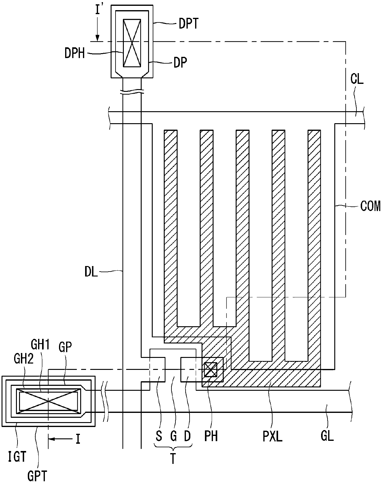
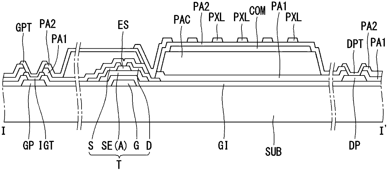
[0055] refer to Figure 5 , we will describe the first embodiment of the present disclosure. Figure 5 is a cross-sectional view showing the structure of the thin film transistor substrate including the oxide semiconductor material according to the first embodiment of the present disclosure. refer to Figure 5 , The thin film transistor substrate according to the first embodiment of the present disclosure includes a plurality of pixel areas including at least one thin film transistor T in each pixel area arranged in a matrix on the substrate SUB. Here, for convenience of explanation, we will mainly explain the structure of the thin film transistor T. FIG.

[0056] On the substrate SUB, a gate G is formed. On the gate G is deposited a gate insulating layer GI covering the entire surface of the substrate SUB. On the gate insulating layer GI, a semiconductor layer A overlapping a middle portion of the gate G is formed. The semiconductor layer A has a stacked structure in whi...

no. 2 approach

[0069] As for the double-layered oxide semiconductor according to the first embodiment, since the channel length is short and has a stable threshold voltage, it is suitable for large-area flat panel displays. However, in the first embodiment, the source S and the drain D directly contact the second oxide semiconductor layer GA. From the viewpoint of electrical characteristics, the resistivity of the second oxide semiconductor layer GA is much larger than that of the first oxide semiconductor layer GO. That is, a thin film transistor having a double-layer oxide semiconductor has greater resistivity and work function than a thin film transistor having a single-layer oxide semiconductor.

[0070] Due to the greater resistivity, contact resistance between the second oxide semiconductor layer GA and the source S and / or between the second oxide semiconductor layer GA and the drain D may be increased. In the first embodiment, a short channel length can be obtained with the double-la...

no. 3 approach

[0078] In the first embodiment and the second embodiment, the source S and the drain D are directly formed on and contact the semiconductor layer A. Referring to FIG. Therefore, the thin film transistor has a back channel etching structure in which the thickness of the channel layer defined between the source S and the drain D of the semiconductor layer A is thinned. In the first embodiment and the second embodiment, only the second oxide semiconductor layer GA is thinned, but the first oxide semiconductor layer GO is not thinned. Therefore, the characteristics of the channel are not affected or deteriorated due to the back channel etch structure. However, for a large-area display panel in which a large number of transistors are disposed on a large-area substrate, it is difficult to form all transistors to have the same or similar conditions and / or dimensions on all regions of the substrate.

[0079] In the third embodiment, we provide a thin film transistor having an etching...


PUM


Abstract

The present disclosure relates to a thin film transistor substrate having a bi-layer oxide semiconductor. The present disclosure provides a thin film transistor substrate comprising: a substrate; andan oxide semiconductor layer on the substrate, wherein the oxide semiconductor layer includes: a first oxide semiconductor layer having indium, gallium and zinc; and a second oxide semiconductor layerstacked on the first oxide semiconductor layer having the indium, gallium and zinc, wherein any one layer of the first and the second oxide semiconductor layers has a first composition ratio of the indium, gallium and zinc of 1:1:1; and wherein other layer has a second composition ratio of the indium, gallium and zinc in which the indium ratio is higher than the zinc ratio.

Description

technical field [0001] The present disclosure relates to a thin film transistor substrate having a bilayer oxide semiconductor. In particular, the present disclosure relates to a thin film transistor substrate of a flat panel display on which two different oxide semiconductor layers are stacked. Background technique [0002] Now, with the development of the information society, the demand for displays that present information is increasing. Accordingly, various flat panel displays (or "FPDs") have been developed to overcome many disadvantages of cathode ray tubes (or "CRTs"), such as heavy weight and bulk. Flat panel display devices include liquid crystal display devices (or "LCD"), field emission displays (or "FED"), plasma display panels (or "PDP"), organic light emitting display devices ("OLED") and electrophoretic display devices (or "ED"). [0003] A display panel of a flat panel display may include a thin film transistor substrate having thin film transistors alloca...

Claims


Application Information

Patent Timeline
Patent Type & Authority Applications(China)
IPC IPC(8): H01L27/12H01L29/786
CPCH01L27/1225H01L29/7869H01L27/1222H01L29/78696H01L29/24H01L29/26
Inventor 李昭珩金圣起李永镇金敏澈梁晸硕任曙延
Owner LG DISPLAY CO LTD
Why Eureka
Try Eureka