
Hybrid precoding method of large-scale MIMO system applied to millimeter wave band

A millimeter-wave frequency band, large-scale technology, applied in the field of millimeter-wave communication technology and multi-antenna, can solve problems such as non-precoding methods and affecting system timeliness

Active Publication Date: 2018-05-11
HANGZHOU DIANZI UNIV
View PDF3 Cites 27 Cited by
  • Summary
  • Abstract
  • Description
  • Claims
  • Application Information

AI Technical Summary

Problems solved by technology

Because complex algorithms will affect the timeliness of the system, these methods are not the best precoding methods in actual operation

Method used


Image

  • Hybrid precoding method of large-scale MIMO system applied to millimeter wave band
  • Hybrid precoding method of large-scale MIMO system applied to millimeter wave band
  • Hybrid precoding method of large-scale MIMO system applied to millimeter wave band

Examples


Embodiment 1

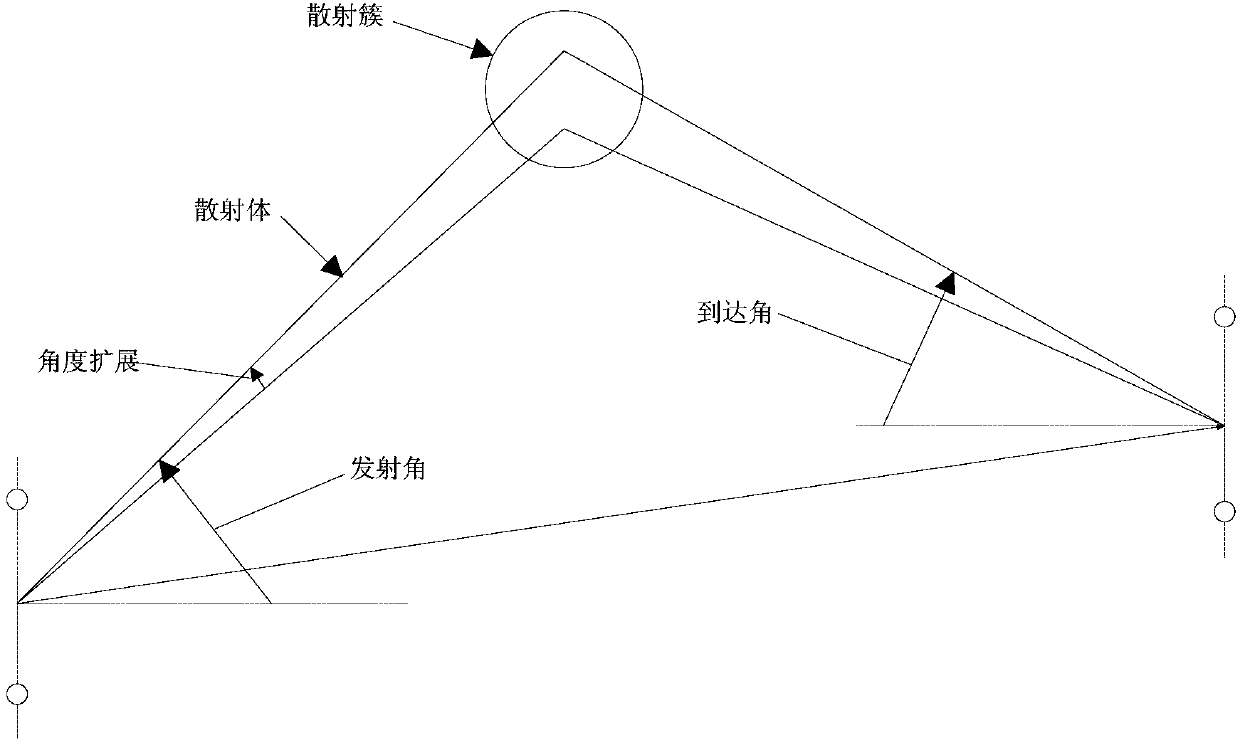
[0046] Set the number of base station antennas to N in the mmWave single-user downlink scenario t =64,N cl = 8 scatter clusters with N in each cluster ray = 10 scatterers, the azimuth angles of AOD and AOA obey the Laplace distribution, and the angular spread is 10°. The number of data streams sent is N s =1,2,3. The receiver has N r = 16 receiving antennas, the number of links at the transmitting end is N RF =4. Assume that the channel uses a ULA array. The signal-to-noise ratio is defined as where ρ is the average received power, σ 2 is the noise power, assuming σ 2 =1. channel is expressed as Perform singular value decomposition (SVD) on channel H to get H=UDV H , take the first N of the right singular matrix V RF The phase angles of the columns are used as the analog precoding matrix F RF Each element in the in means N t ×N RF The phase of the ijth element in the dimensional matrix. Also take the first N of the right singular matrix V s Columns are ...

Embodiment 2

[0049] Set the number of base station antennas to N in the mmWave single-user downlink scenario t =256,N cl = 8 scatter clusters with N in each cluster ray = 10 scatterers, the azimuth angles of AOD and AOA obey the Laplace distribution, and the angular spread is 10°. The number of data streams sent is N s =1,2,3. The receiver has N r = 64 receiving antennas, the number of links at the transmitting end is N RF =5. Assume that the channel uses a ULA array. The signal-to-noise ratio is defined as where ρ is the average received power, σ 2 is the noise power, assuming σ 2 =1. channel is expressed as Perform singular value decomposition (SVD) on channel H to get H=UDV H , take the first N of the right singular matrix V RF The phase angles of the columns are used as the analog precoding matrix F RF Each element in the in means N t ×N RFThe phase of the ijth element in the dimensional matrix. Also take the first N of the right singular matrix V s Columns are ...


PUM


Abstract

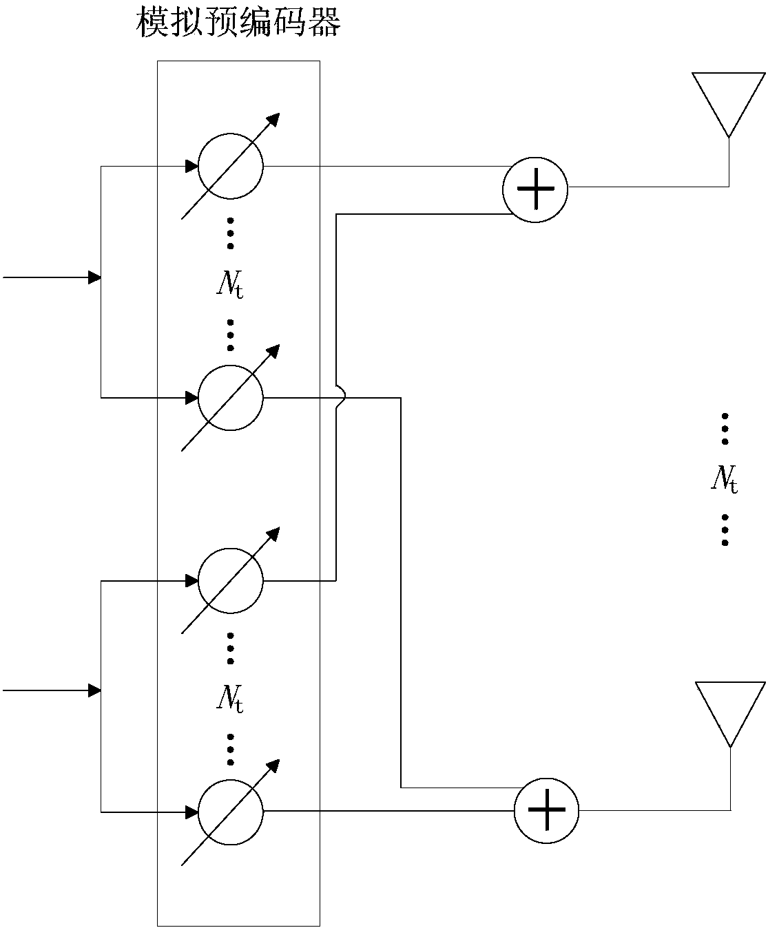
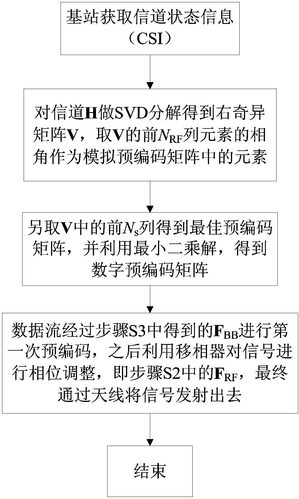
The invention discloses a hybrid precoding method of a large-scale MIMO system applied to a millimeter wave band. The method comprises the following steps: S1: obtaining, by a base station, channel state information (CSI); S2: performing SVD on a downlink channel to obtain a right singular matrix V, using a phase angle of a former NRF column of the V as each element in an analog precoding matrix FRF, wherein NRF represents the number of radio frequency links; S3: using former Ns columns of the right singular matrix V subjected to the SVD on the downlink channel as an optimal precoding matrix Fopt, and obtaining a digital precoder (the formula is described in the specification) according to the Fopt and the FRF by using a least-squares solution (LS), wherein Ns represents the number of datastreams; and S4: performing first time precoding on the data streams through the FBB obtained in the step S3, then performing phase adjustment on a signal, namely, the FRF in the step S2, by using aphase shifter, and finally transmitting the signal through an antenna. Compared with the prior art, the hybrid precoding method disclosed by the invention has the advantages that no optimization method or complicated iterative algorithm is needed, so that the complexity is greatly reduced, and higher spectral efficiency can be achieved.

Description

technical field [0001] The invention belongs to the field of millimeter wave communication technology and multi-antenna technology, and relates to a hybrid precoding method for improving system spectrum efficiency, in particular to a massive MIMO system hybrid precoding method applied in the millimeter wave frequency band. Background technique [0002] With the rapid development of the information age, people put forward higher requirements for faster and more efficient data transmission. However, the existing communication in the frequency band below 10 GHz can no longer meet the future communication needs, which also makes more and more scholars turn their research targets to the millimeter wave communication in the higher frequency band (30 GHz-300 GHz). Due to the high frequency band and short wavelength of the millimeter wave, developers can deploy a large number of antennas at both ends of the transceiver, which also makes up for the serious path loss problem caused by...

Claims


Application Information

Patent Timeline
Patent Type & Authority Applications(China)
IPC IPC(8): H04B7/0413H04B7/0456H04B7/06
CPCH04B7/0413H04B7/0456H04B7/0626
Inventor 张丹潘鹏王海泉尤若楠
Owner HANGZHOU DIANZI UNIV
Learn More