Roller centrifugal type environment-friendly treatment device for sludge dewatering

A sludge dehydration and environmental protection treatment technology, applied in water/sludge/sewage treatment, sludge treatment, dehydration/drying/thickened sludge treatment, etc. Reduce dehydration efficiency and other issues, to achieve the effect of increasing dehydration efficiency, novel design and reasonable structure

Inactive Publication Date: 2018-05-15
TIANJIN ZHONGTIAN JINGKE SCI & TECH
View PDF6 Cites 28 Cited by
  • Summary
  • Abstract
  • Description
  • Claims
  • Application Information

AI Technical Summary

Problems solved by technology

At present, the most used sludge dewatering machine in the market is the screw stacking sludge dewatering machine, but the screw stacking sludge dewatering machine is easy to cause sludge to block the filter screen when it is used, which greatly reduces the dehydration efficiency. After sludge dehydration, it is difficult to take out and recycle the dehydrated sludge, which seriously affects the quality of sludge treatment in the later stage, and is not very practical.

Method used

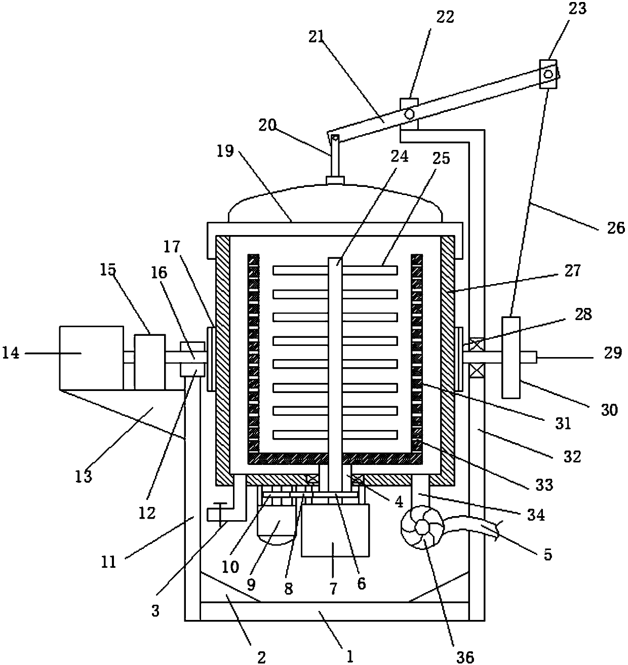
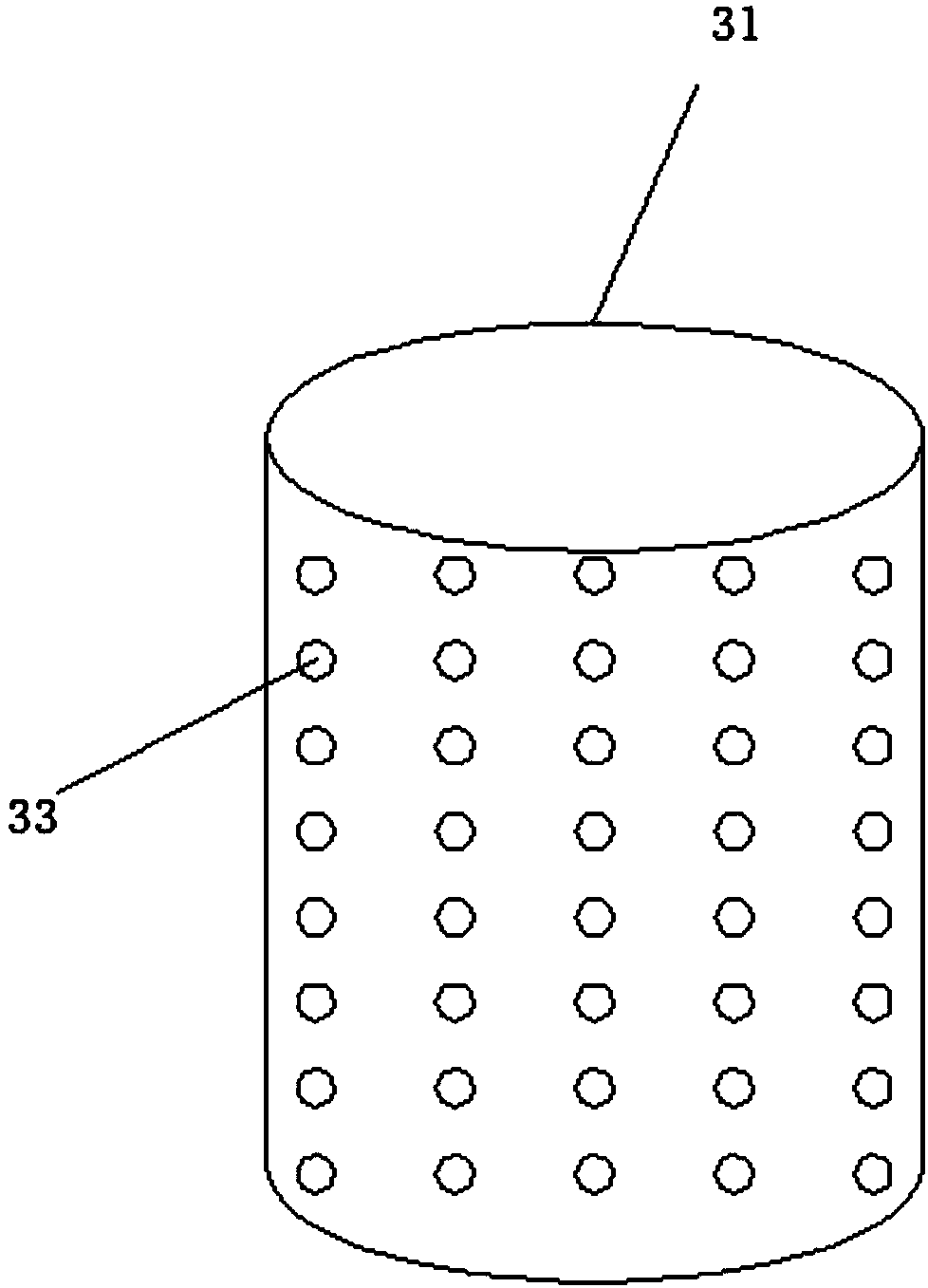
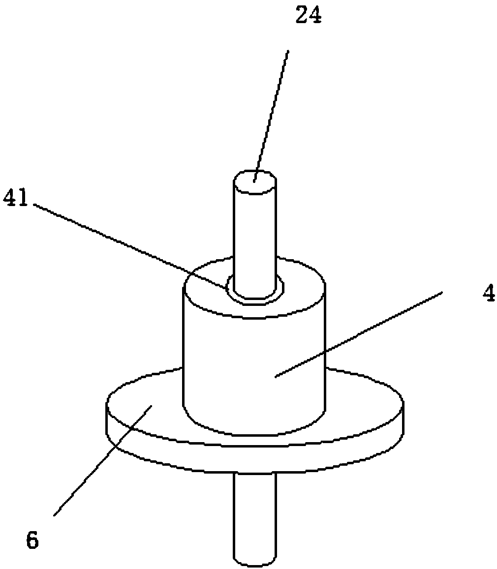

Image

  • Roller centrifugal type environment-friendly treatment device for sludge dewatering
  • Roller centrifugal type environment-friendly treatment device for sludge dewatering
  • Roller centrifugal type environment-friendly treatment device for sludge dewatering

Examples


Embodiment Construction

[0022] It should be noted that, in the case of no conflict, the embodiments of the present invention and the features in the embodiments can be combined with each other.

[0023] In describing the present invention, it should be understood that the terms "center", "longitudinal", "transverse", "upper", "lower", "front", "rear", "left", "right", " The orientations or positional relationships indicated by "vertical", "horizontal", "top", "bottom", "inner" and "outer" are based on the orientations or positional relationships shown in the drawings, and are only for the convenience of describing the present invention and Simplified descriptions, rather than indicating or implying that the device or element referred to must have a particular orientation, be constructed and operate in a particular orientation, and thus should not be construed as limiting the invention. In addition, the terms "first", "second", etc. are used for descriptive purposes only, and should not be understood ...


PUM


Abstract

The invention discloses a roller centrifugal type environment-friendly treatment device for sludge dewatering. The device comprises a fixing base plate; a first supporting frame is arranged on the left side of the upper end of the fixing base plate; a guide base is arranged at the upper end of the first supporting frame; a driving shaft is arranged in the middle of the guide base; a first rotatingdisc is arranged at the right end of the driving shaft; a second supporting frame is arranged on the right side of the upper end of the fixing base plate; a driven shaft is arranged in the middle ofthe second supporting frame through a bearing; a second rotating disc is arranged at the left end of the driven shaft; an outer cylinder is arranged between the first rotating disc and the second rotating disc; a first motor is arranged on the left side of the lower end of the outer cylinder; a driving belt wheel is arranged at the upper end of the first motor; a driven belt wheel is connected tothe right end of the driving belt wheel through a belt; a main shaft is arranged at the upper end of the driven belt wheel; an inner cylinder is arranged at the upper end of the main shaft; and a counter shaft is arranged in the main shaft. According to the device, sludge can be efficiently dewatered by utilizing the centrifugal force, the dewatering efficiency of the sludge can be improved, and meanwhile, the dewatered sludge can be quickly poured out.

Description

technical field [0001] The invention relates to the technical field of environmental protection equipment, in particular to a drum centrifugal sludge dehydration environmental protection treatment device. Background technique [0002] Sludge is the product of sewage treatment, which is an extremely complex heterogeneous body composed of organic debris, bacterial cells, inorganic particles, colloidal sludge, etc. The main characteristics of sludge are high water content (up to 99%), high content of organic matter, easy to rot and smell, and the particles are finer, the specific gravity is smaller, and it is in a colloidal liquid state. It is a thick substance between liquid and solid, which can be transported by pump, but it is difficult to separate solid and liquid by sedimentation. Sludge usually refers to the precipitated sludge, particulate matter and floating matter produced when wastewater is treated by physical, chemical, physicochemical and biological methods. Sludg...

Claims


Application Information

Patent Timeline
Patent Type & Authority Applications(China)
IPC IPC(8): C02F11/12B04B1/00B04B9/02B04B11/04
CPCB04B1/00B04B9/02B04B11/04C02F11/127
Inventor 李绩
Owner TIANJIN ZHONGTIAN JINGKE SCI & TECH
Why Eureka
Try Eureka