Piezoelectric element, piezoelectric sensor as well as speed and displacement detecting device

A piezoelectric sensor and piezoelectric element technology, applied in the field of sensing and testing, can solve the problems of few sensors, high price, complex measurement system, etc., achieve high measurement accuracy and frequency response, improve measurement accuracy, and reduce charge leakage Effect

Active Publication Date: 2018-05-15
GENERAL ENG RES INST CHINA ACAD OF ENG PHYSICS
View PDF24 Cites 0 Cited by
  • Summary
  • Abstract
  • Description
  • Claims
  • Application Information

AI Technical Summary

Problems solved by technology

The laser displacement sensor has a large volume. Although the volume of the capacitance micrometer and the eddy current sensor can be on the order of centimeters, these sensors still cannot be used for displacement measurement in a very narrow space. and install very harsh
In addition, for displacement measurement with high precision (submicron and nanometer level) and high frequency response (up to kilohertz), traditional laser displacement sensors, capacitance micrometers, etc. are very expensive.
[0005] On the other hand, currently known rotation speed measurement generally adopts grating or other methods, but for the measurement of linear velocity, there are fewer corresponding sensors, especially for the high-frequency response and high-precision linear velocity measurement of reciprocating motion. Puller sensors are very expensive and the measurement system is complex

Method used


Image

  • Piezoelectric element, piezoelectric sensor as well as speed and displacement detecting device
  • Piezoelectric element, piezoelectric sensor as well as speed and displacement detecting device
  • Piezoelectric element, piezoelectric sensor as well as speed and displacement detecting device

Examples


Embodiment Construction

[0026] The principles and features of the present invention are described below in conjunction with the accompanying drawings, and the examples given are only used to explain the present invention, and are not intended to limit the scope of the present invention.

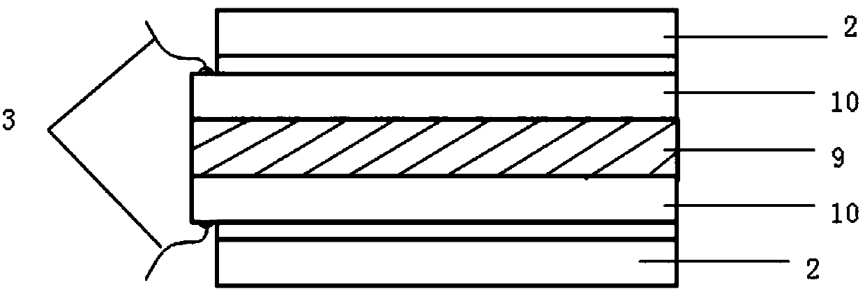
[0027] Such as figure 1 As shown, the present invention relates to a piezoelectric element based on a piezoelectric film, including a piezoelectric sheet 1, and the piezoelectric sheet 1 includes a piezoelectric film layer 9, an electrode layer 10 arranged on the upper and lower surfaces of the piezoelectric film layer 9 , and an insulating layer 2 covering the outer surface of each electrode layer 10; each electrode layer 10 leads out a signal line 3.

[0028] The piezoelectric sheet 1 has a triangular shape and is a flexible piezoelectric sheet, and the insulating layer is a flexible insulating layer. The piezoelectric film layer 9 is a PVDF piezoelectric film.

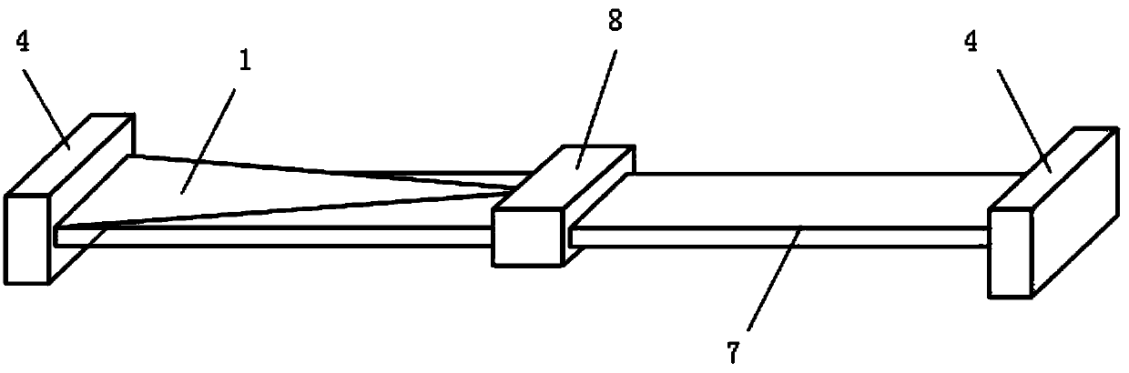
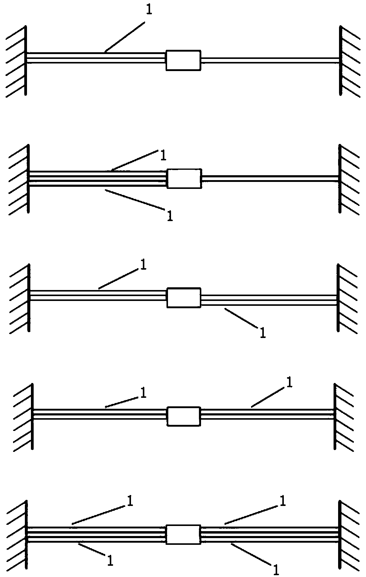
[0029] Such as figure 2 , image 3 As shown, a...


PUM


Abstract

The invention relates to a piezoelectric element, a piezoelectric sensor as well as a speed and displacement detecting device. The piezoelectric element comprises a piezoelectric plate, wherein the piezoelectric plate comprises a piezoelectric film layer, electrode layers arranged on the upper surface and the lower surface of the piezoelectric film layer as well as insulating layers covering the outer surfaces of all the electrode layers; a signal wire is led from each electrode layer; the piezoelectric sensor comprises the piezoelectric element and a flexible mechanism; the flexible mechanismcomprises a base as a measuring head of the sensor and flexible substrates embedded in two sides of the base; the piezoelectric element is stuck on the surface of at least any one flexible substrate;in addition, the bottom end of the piezoelectric element is aligned to one end of the flexible substrate; the top end of the piezoelectric element is aligned to the edge of the base. The speed and displacement detecting device comprises the piezoelectric sensor; one signal wire is connected with a positive electrode of a charge amplifier and a positive electrode of a current amplifier; the othersignal wire is connected with a negative electrode of the charge amplifier and a negative electrode of the current charger. The piezoelectric element and the piezoelectric sensor can meet the measurement demands with harsh volume requirements of high precision and high frequency response on displacement and linear velocity.

Description

technical field [0001] The invention belongs to the technical field of sensing and testing, and in particular relates to a piezoelectric element, a piezoelectric sensor and a speed and displacement detection device. Background technique [0002] Piezoelectric films, such as known PVDF piezoelectric sheets, known piezoelectric fibers, etc., are widely used in the manufacture of sensors due to their excellent flexibility and bendability. The basic principle of piezoelectric sensors is based on the positive piezoelectric effect of piezoelectric materials, that is, external force or displacement induces strain on the piezoelectric sheet, and then generates charges on the surface of the piezoelectric sheet. The advantages of piezoelectric sensors are high precision and high frequency response, especially suitable for dynamic measurement. [0003] Currently known piezoelectric sheets are widely used in the measurement of wind speed, strain, force and vibration acceleration. For ...

Claims


Application Information

Patent Timeline
Patent Type & Authority Applications(China)
IPC IPC(8): H01L41/08H01L41/113H01L41/193G01D21/02
CPCG01D21/02H10N30/1051H10N30/308H10N30/302H10N30/857
Inventor 凌明祥刘谦黎启胜李思忠田光明岳新武蒋宁
Owner GENERAL ENG RES INST CHINA ACAD OF ENG PHYSICS
Why Eureka
Try Eureka