Device for machining copper foil hole through laser

A laser processing and laser drilling technology, which is applied in laser welding equipment, metal processing equipment, manufacturing tools, etc., can solve the problems of high loss of drill bits, difficulty in chip removal, and inability to achieve high-efficiency processing.

Inactive Publication Date: 2018-05-18
CHINA SOUTH IND GRP AUTOMATION RES INST
View PDF13 Cites 9 Cited by
  • Summary
  • Abstract
  • Description
  • Claims
  • Application Information

AI Technical Summary

Problems solved by technology

In other small hole processing methods, such as common drilling, there are long processing time, high drill loss, difficult chip removal, and the inability to efficiently process small holes in batches of planar arrays; EDM also has difficulties in controlling the processing process, The processing accuracy of tiny holes cannot be guaranteed, and the size value of the processing process cannot be monitored and adjusted.

Method used


Image

  • Device for machining copper foil hole through laser

Examples


Embodiment 1

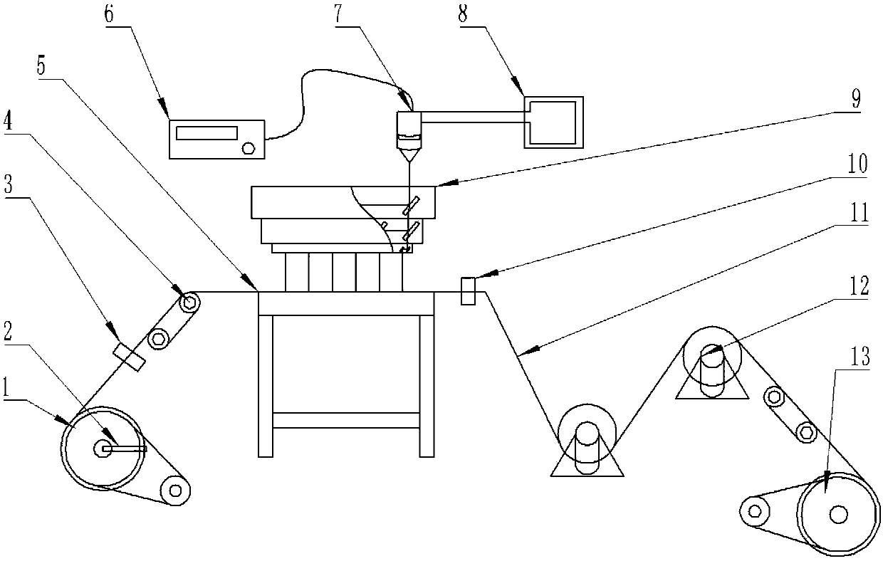
[0036] Such as figure 1 As shown, a device for laser processing copper foil holes, including a control system, a laser 6 and a motion system;

[0037] The control system is used to control the motion system to work;

[0038] The motion system is used to drive the copper foil through the laser drilling point of the laser 6;

[0039] The motion system includes a copper foil transmission mechanism and a support frame 5, the top of the support frame 5 is provided with a punching table, and the copper foil transmission mechanism is used to make the copper foil pass through the punching table in sequence;

[0040] Also includes a tension sensor 10, the tension sensor 10 is used to detect the tension on the copper foil during the copper foil transfer process, and the data output end of the tension sensor 10 is connected with the signal input end of the control system, and the control system is based on the tension obtained by the tension sensor 10 The data controls the working stat...

Embodiment 2

[0044] Such as figure 1 As shown, this embodiment is further limited on the basis of Embodiment 1: As a specific implementation of the copper foil transmission mechanism, the copper foil transmission mechanism includes a winding wheel 1 and an unwinding wheel 13;

[0045] The winding wheel 1 is used for winding the laser-perforated copper foil, and the winding wheel 1 is also connected with a driving device for driving the winding wheel 1 to rotate;

[0046] The unwinding wheel 13 is used to fix the copper foil roll to be released;

[0047] It also includes a tension wheel 12, and also includes a position adjustment device or a damping device, and the wheel surface of the tension wheel 12 serves as a constraint surface for the copper foil movement path during the copper foil transfer process;

[0048] The position adjusting device is connected with the tension wheel 12, and is used to change the position of the tension wheel 12 wheel surface in space;

[0049] The damping de...


PUM


Abstract

The invention discloses a device for machining a copper foil hole through a laser. The device for machining the copper foil hole through the laser comprises a control system, a laser device and a motion system. The control system is used for controlling the motion system to work. The motion system is used for driving copper foil to pass through a laser punching point of the laser device. The motion system comprises a copper foil conveying mechanism and a supporting frame. The top of the supporting frame is provided with a punching worktable. The copper foil conveying mechanism is used for making the copper foil sequentially pass through the punching worktable. The device for machining the copper foil hole through the laser further comprises a tension sensor. The tension sensor is used fordetecting the tension on the copper foil in the conveying process of the copper foil, and the data output end of the tension sensor is connected with the signal input end of the control system. The control system controls a working state of the copper foil conveying mechanism according to tension data obtained by the tension sensor. The device for machining the copper foil hole through the laser is used for conducting laser punching machining on the copper foil, and the obtained hole in the copper foil can be made to have higher position precision.

Description

technical field [0001] The invention relates to the technical field of hole processing equipment, in particular to a device for laser processing copper foil holes. Background technique [0002] Using laser to process tiny holes is one of the main application fields of laser processing. In laser processing, it is classified as laser removal, also called evaporation processing. Laser processing mainly relies on photochemical corrosion and photothermal combustion, and the processed material absorbs high-energy laser , Processing thin and deep holes in a very short time, using this technology can process a vertical micro-hole array on the plate. [0003] In recent years, with the rapid development of science and technology, in industries such as aerospace, aviation, electronics, pharmaceuticals, food, textiles, instruments and medical equipment, there are more and more parts with small holes, and the materials of these parts are various. , both metals and non-metals, and many d...

Claims


Application Information

Patent Timeline
Patent Type & Authority Applications(China)
IPC IPC(8): B23K26/382B23K26/70B23K103/12
CPCB23K26/382B23K26/702
Inventor 钟诚王敏陈昌金尹健范华献钟金龙王新科李宝林
Owner CHINA SOUTH IND GRP AUTOMATION RES INST
Why Eureka
Try Eureka