[0022] The specific embodiments of the present invention will be described in detail below with reference to the accompanying drawings. It should be understood that the specific embodiments described herein are only used to illustrate and explain the present invention, but not to limit the present invention.
[0023] In the present invention, unless otherwise stated, the orientation words such as "upper, lower, inner, outer" included in a term only represent the orientation of the term under normal usage, or are understood by those skilled in the art and should not be viewed as a limitation of the term.
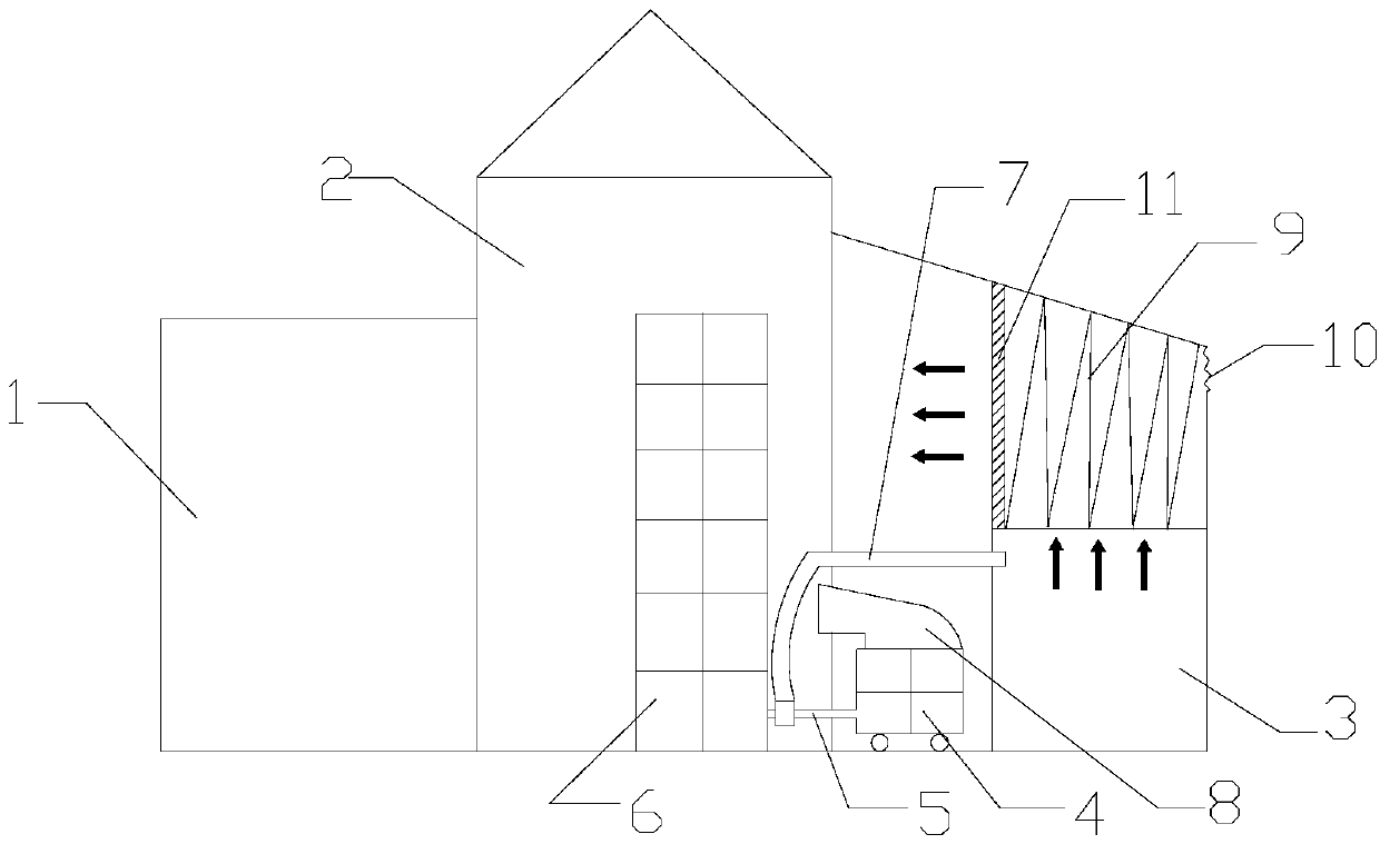
[0024] The invention provides a double-effect grain drying center system for dust removal and waste heat recovery, such as figure 1 As shown, including wet granary 1, drying room 2, transition room, and ash room 3 successively arranged in sequence, drying room 2 is provided with dryer 6, transition room is provided with heat pump hot blast stove 4, heat pump hot blast stove 4 The hot air outlet is communicated with the dryer 6 through the air energy supply pipe 5. The air energy supply pipe 5 is branched with a dust discharge and exhaust pipe 7 to communicate with the ash room 3. The top of the ash room 3 is arranged with a wave-shaped dust removal. Mechanism 9, the dust exhaust pipe 7 is located below the wave-shaped dust removal mechanism 9, and the top of the ash room 3 is connected with the top of the transition room.
[0025] The above-mentioned dust removal and waste heat recovery double-effect grain drying center system ensures that the dust will not be further flying by setting the drying room 2, the transition room and the ash room 3; secondly, its specific working process is: first, start the heat pump hot blast stove 4 , the hot air generated by it is transported to the drying room 2 through the air energy supply pipe 5 to dry the grain, and at the same time, the hot air with dust returned from the drying room 2 is discharged into the ash room 3 through the dust exhaust pipe 7 Purify; once the hot air with dust enters the ash room 3, the hot air passes through the wave-shaped dust removal mechanism 9 and then goes further to the transition room to preheat the heat pump hot blast stove 4, thereby effectively achieving the effect of heat recovery; more Most importantly, in the process of heat recovery, it can also play the role of dust removal; in addition, the supplementary air outlet 10 can supply fresh air for the transition room, and the fresh air is dedusted by the wave-shaped dust removal mechanism 9 . Therefore, the grain drying center has excellent dual effects of dust removal and waste heat recovery.
[0026] In the present invention, the specific structure of the wave-shaped dust removal mechanism 9 can be selected in multiple ways, but in order to make it have excellent dust removal effect and consider economic conditions, preferably, the wave-shaped dust removal mechanism 9 is composed of dust removal cloth bags.
[0027] In this embodiment, in order to further dedust the hot air and fresh air in the ash room 3, preferably, a primary filter 11 is provided at the connection between the top of the ash room 3 and the top of the transition room. The hot air and fresh air passed through the primary filter 11 can have an excellent dust removal effect.
[0028] In the present invention, the specific position of the supplementary air outlet 10 on the ash room 3 can be selected within a wide range, but in order to enable the fresh air in the supplementary air outlet 10 to enter the transition room in time, and also to perform timely dust removal, preferably Ground, the supplementary air outlet 10 is arranged on the top of the ash room 3 and the supplementary air outlet 10 faces the wave-shaped dust removal mechanism 9 .
[0029] At the same time, the specific installation position of the air energy supply pipe 5 can also be selected in a wide range, but in order to enable the hot air entering the dryer 6 to fully dry the grain, preferably, the air energy supply pipe Both ends of 5 are respectively arranged at the bottom of the heat pump hot blast stove 4 and the bottom of the dryer 6 . Then, the hot air can dry the grain from the bottom of the dryer 6, which can optimize the drying effect.
[0030] On the basis of the above embodiment, the discharge position of the cold air at the condensation end of the heat pump hot blast stove 4 can also be selected in a wide range, but in order to allow the cold air to be discharged in time, preferably, the cold air duct 8 at the condensation end of the heat pump hot blast stove 4 Connected to drying room 2.
[0031] The preferred embodiments of the present invention have been described in detail above with reference to the accompanying drawings. However, the present invention is not limited to the specific details of the above-mentioned embodiments. Within the scope of the technical concept of the present invention, various simple modifications can be made to the technical solutions of the present invention, These simple modifications all belong to the protection scope of the present invention.
[0032] In addition, it should be noted that the specific technical features described in the above-mentioned specific embodiments can be combined in any suitable manner under the condition of no contradiction. In order to avoid unnecessary repetition, the present invention has The combination method will not be specified otherwise.
[0033] In addition, the various embodiments of the present invention can also be combined arbitrarily, as long as they do not violate the spirit of the present invention, they should also be regarded as the contents disclosed in the present invention.