Velocity measurement apparatus and method of single photon avalanche detector linear array camera

A single-photon avalanche, line scan camera technology, applied to devices using optical methods, etc., can solve the problems of unfavorable data real-time processing, CCD and CMOS data loss, large video data volume, etc. Longitudinal resolution, accurate speed measurement effect

Inactive Publication Date: 2018-05-18
NANJING UNIV
View PDF11 Cites 3 Cited by
  • Summary
  • Abstract
  • Description
  • Claims
  • Application Information

AI Technical Summary

Problems solved by technology

Ground induction coil speed measurement requires the coil to be installed underground, which will damage the road surface during construction, and is easily deformed by the environment, and the actual maintenance cost is relatively high
[0005] Video speed measurement is based on imaging means, and then uses image processing to achieve speed measurement, but the video speed measurement method is limited by external conditions such as lighting, and the amount of video data is large, which is not conducive to real-time data processing
[0006] The existing linear array camera speed measurement system generally uses ordinary CCD or CMOS linear array as the imaging device to measure the speed, but the ordinary CCD or CMOS uses A / D conversion to read data, which is affected by the analog-to-digital converter (ADC) and The full well of the device is limited, and its dynamic range of light intensity is very limited. It is necessary to change the camera sensitivity or change the exposure time to achieve imaging of different ambient light intensities. When the ambient light intensity changes very quickly, CCD and CMOS may be sensitive to If the speed change is not timely, the phenomenon of data loss will occur

Method used


Image

  • Velocity measurement apparatus and method of single photon avalanche detector linear array camera
  • Velocity measurement apparatus and method of single photon avalanche detector linear array camera
  • Velocity measurement apparatus and method of single photon avalanche detector linear array camera

Examples


Embodiment Construction

[0027] In the following detailed description, the working principle, device and working method of the present invention will be described in detail with reference to the drawings and implementation results.

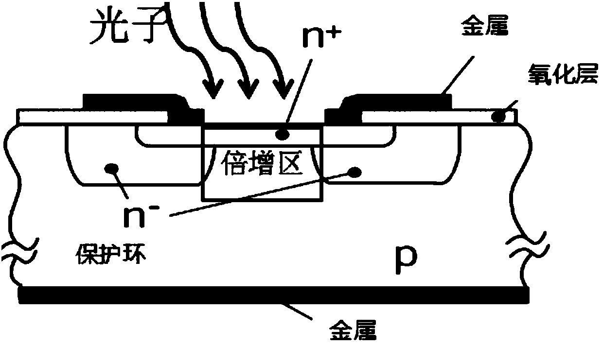
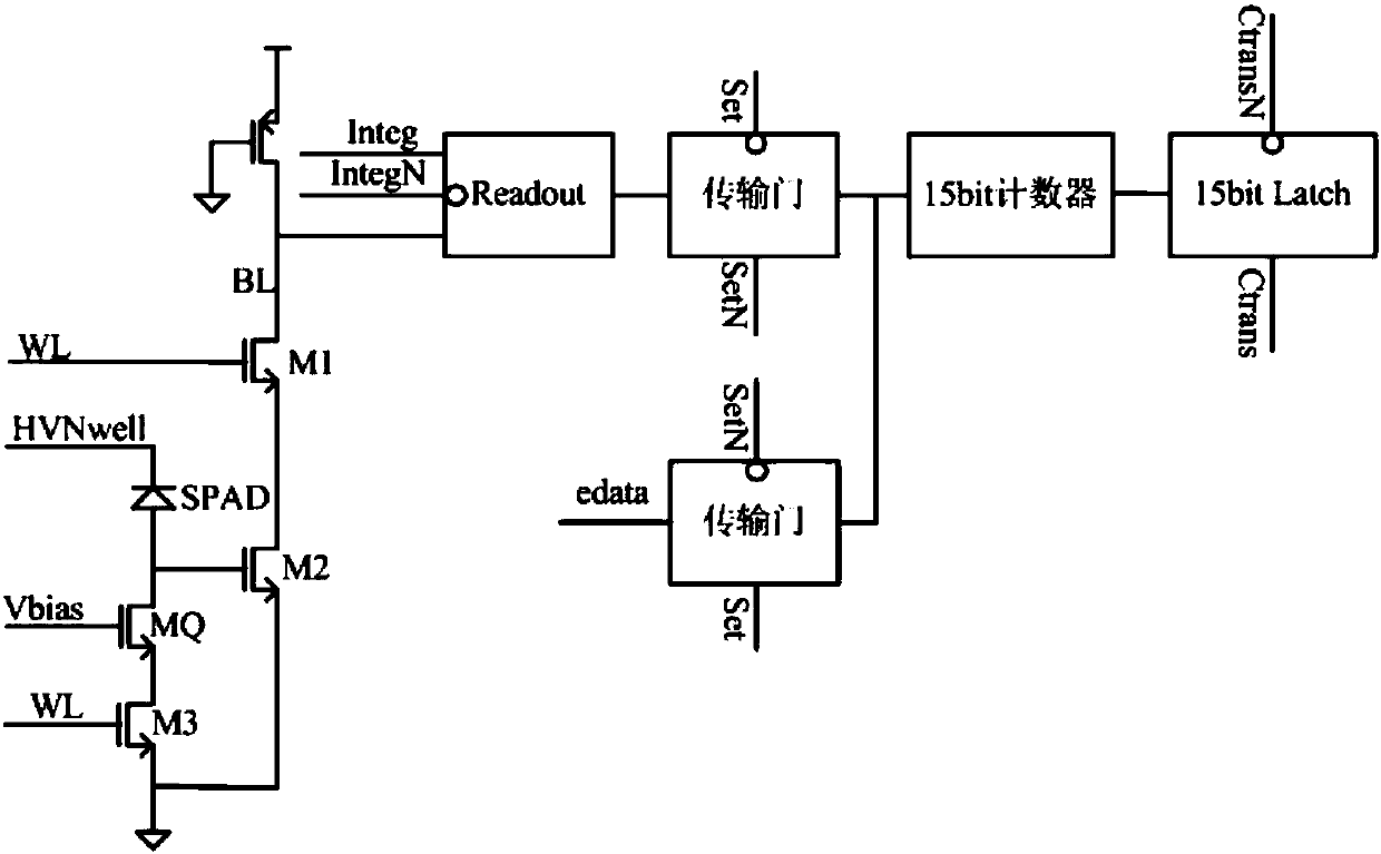
[0028] In this embodiment, the SPAD line array camera and the object to be photographed are placed at a certain angle to scan and photograph the moving object, and the moving speed of the object is obtained by calculating the relationship between the known object size and the corresponding imaging size. The speed measuring device used is a line array camera made of a single photon avalanche detector line array. The single photon avalanche detector line array includes a plurality of detector units, and the detector unit includes a single photon avalanche detector, a quenching and reset circuit, The counter and the register, the output terminal of the single photon avalanche detector is connected to the quenching and reset circuit and the counter in turn, and the output term...


PUM


Abstract

The invention provides a velocity measurement apparatus and method of a single photon avalanche detector linear array camera. The velocity measurement apparatus and method of a single photon avalanchedetector linear array camera are characterized in that single photon avalanche detectors are used to form a linear array camera for an imaging device to measure the velocity, and the velocity of a moving object is calculated by means of the known size of the object, the corresponding vertical pixel number in the image, the camera single row shooting integral time and the camera shooting angle; the unit of the single photon avalanche detector linear array includes a single photon avalanche detector, a quenching and resetting circuit, a counter and a dwell vessel; the output terminal of the single photon avalanche detector is connected with the quenching and resetting circuit, and the counter successively; the output terminal of the counter is connected with the dwell vessel; and the singlephoton avalanche detector utilizes a single photon avalanche diode. The velocity measurement apparatus and method of a single photon avalanche detector linear array camera has the advantages of realizing velocity measurement in the daytime with strong illumination, the night with weak illumination and the extremely dark environment, and being more accurate in velocity measurement.

Description

technical field [0001] The invention relates to a speed measuring device and method for a moving target, in particular to a speed measuring method using imaging technology. Background technique [0002] At present, the main speed measurement technologies for moving targets include microwave radar monitoring technology, laser detection technology, ground sensing coil speed measurement and video speed measurement, etc. [0003] Microwave radar monitoring technology mainly uses the Doppler Effect principle: when the target approaches the radar antenna, the frequency of the reflected signal will be higher than that of the transmitter; conversely, when the target moves away from the antenna, the frequency of the reflected signal will be lower. on the transmission probability. In this way, the relative speed between the target and the radar can be calculated by changing the value of the frequency. However, the reception and emission of electromagnetic waves by this technology are...

Claims


Application Information

Patent Timeline
Patent Type & Authority Applications(China)
IPC IPC(8): G01P3/38
CPCG01P3/38
Inventor 卜晓峰孔祥顺闫锋毛成李张南李煜乾黄枝建杨程马浩文张丽敏
Owner NANJING UNIV
Why Eureka
Try Eureka