Test circuit and test method of parallel MOSFET inversion module

An inverter module and test circuit technology, applied in the field of inverter module testing, can solve the problems of inability to confirm the use of the module, too many electronic devices, and difficult MOSFET reliability, etc., and achieve the effects of reliable testing methods and simple testing circuits.

Active Publication Date: 2018-05-18
CHERY AUTOMOBILE CO LTD
View PDF6 Cites 5 Cited by
  • Summary
  • Abstract
  • Description
  • Claims
  • Application Information

AI Technical Summary

Problems solved by technology

[0004] Although separate MOSFETs have many advantages in parallel connection, due to the large number of electronic devices after parallel connection, the welding process is difficult to ensure the reliability of all MOSFETs, and it is difficult to confirm the actual use of the modules after parallel connection.

Method used


Image

  • Test circuit and test method of parallel MOSFET inversion module

Examples


Embodiment 1

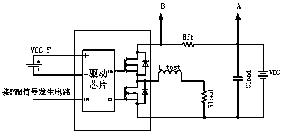
[0017] As shown in the figure, the inverter module to be tested in this embodiment is composed of an inverter module to be tested, a load circuit, a main power supply, an auxiliary power supply, and a PWM signal generating circuit; the inverter module to be tested is composed of a driver chip, two MOSFETs The source of the first MOSFET is connected to the drain of the second MOSFET, and the driver chip has two output terminals, which are respectively connected to the gates of the two MOSFETs. The driver chip receives the PWM signal generating circuit PWM signal, and send PWM driving signals with opposite phases to the gates of the two MOSFETs; the source of the first MOSFET is used as the power supply terminal of the inverter module to be tested, and the drain of the second MOSFET is used as the inverter to be tested The ground terminal of the module, the source and drain of the two MOSFET tubes are connected through a diode, and the conduction direction of the diode is from th...


PUM


Abstract

The invention aims at providing a test circuit and test method of a parallel MOSFET (Metal-Oxide-Semiconductor Field-Effect Transistor) inversion module, for testing the functionality of the parallelMOSFET inversion module and looking for the corresponding hidden trouble. The test circuit of the parallel MOSFET inversion module is formed by an inversion module to be tested, a load circuit, a primary power supply, an auxiliary power supply and a PWM signal generation circuit, wherein the output terminal of the PWM signal generation circuit is connected with the input terminal of the inversionmodule to be tested; two ends of the primary power supply are respectively connected with the power terminal of the inversion module to be tested and the ground terminal of the inversion module to betested to form a closed loop; the load circuit is formed by an adjusting resistor, a load inductor, a load resistor and a load capacitor, and the adjusting resistor is connected between the power terminal of the inversion module to be tested and the primary power supply in series; the series circuit formed by the load inductor and the load resistor is connected between the output terminal and theground terminal of the inversion module to be tested in series, and the load capacitor and the primary power supply are connected in parallel; and the positive and negative terminals of the auxiliarypower supply are respectively connected with the positive and negative power pins of a drive chip in the inversion module to be tested.

Description

technical field [0001] The invention relates to a test of an inverter module, in particular to a test circuit and a test method of a parallel MOSFET inverter module of a motor controller for an electric vehicle. Background technique [0002] In recent years, as global oil resources become increasingly tense and environmental pollution becomes more and more serious, the voice of developing green and energy-saving new energy vehicles is getting louder and louder. Electric vehicles, as the fastest-growing and most technologically mature new energy vehicles, are gradually appearing in people's sights. The power system of an electric vehicle is different from the engine and gearbox of a traditional car. It mainly includes batteries, motors and motor controllers. [0003] The high-power inverter module of the motor controller is its core component, which not only plays an important role in the work of the controller, but also is expensive and fragile. High voltage or long-term h...

Claims


Application Information

Patent Timeline
Patent Type & Authority Applications(China)
IPC IPC(8): G01R31/26
CPCG01R31/26
Inventor 杭孟荀邵平林伟义吴瑞魏昌田袁文爽
Owner CHERY AUTOMOBILE CO LTD
Why Eureka
Try Eureka