
Intelligent multi-rotor UAV based on on-board computer and realization method thereof

A multi-rotor unmanned aerial vehicle, airborne computer technology, applied in the direction of rotorcraft, motor vehicles, instruments, etc., can solve the problems of poor maneuverability, high crash rate, limited application of multi-rotor unmanned aerial vehicles, etc., reaching the level of human-machine communication Improvements in lift, reliability and maintainability

Inactive Publication Date: 2018-05-22
郑宏远
View PDF12 Cites 22 Cited by
  • Summary
  • Abstract
  • Description
  • Claims
  • Application Information

AI Technical Summary

Problems solved by technology

[0007] To sum up, since the current multi-rotor UAVs can only realize simple automatic flight functions such as target following, automatic landing, automatic hovering and simple obstacle avoidance, it is only a simple supplement to the manual remote control operation method or makes the operation change. It is relatively simple, and the main body of the operation of the UAV is still a human being, so the UAV should deal with unknown obstacles and signal interference (including remote control and satellite positioning signals), communication system, target position movement or disappearance encountered during the flight, etc. In case of unexpected problems, we can only mechanically rely on the pre-input program, and the crash rate is very high. The machine vision algorithms currently used in the field of multi-rotor UAVs are limited by the computing power of the flight control board. The algorithms used are relatively simple, and the recognition effect is limited. , and the effect of manual remote control of the drone is greatly affected by the field of view of the onboard camera mechanism, the delay time of the image transmission and digital transmission equipment, and the response speed of the operator. The actual effect shown is that the response of the drone is slow, maneuvering Poor, does not have the ability to maneuver to chase fast moving targets
Therefore, the application of multi-rotor UAVs in industrial and military fields is greatly limited.

Method used


Image

  • Intelligent multi-rotor UAV based on on-board computer and realization method thereof
  • Intelligent multi-rotor UAV based on on-board computer and realization method thereof
  • Intelligent multi-rotor UAV based on on-board computer and realization method thereof

Examples


Embodiment 1

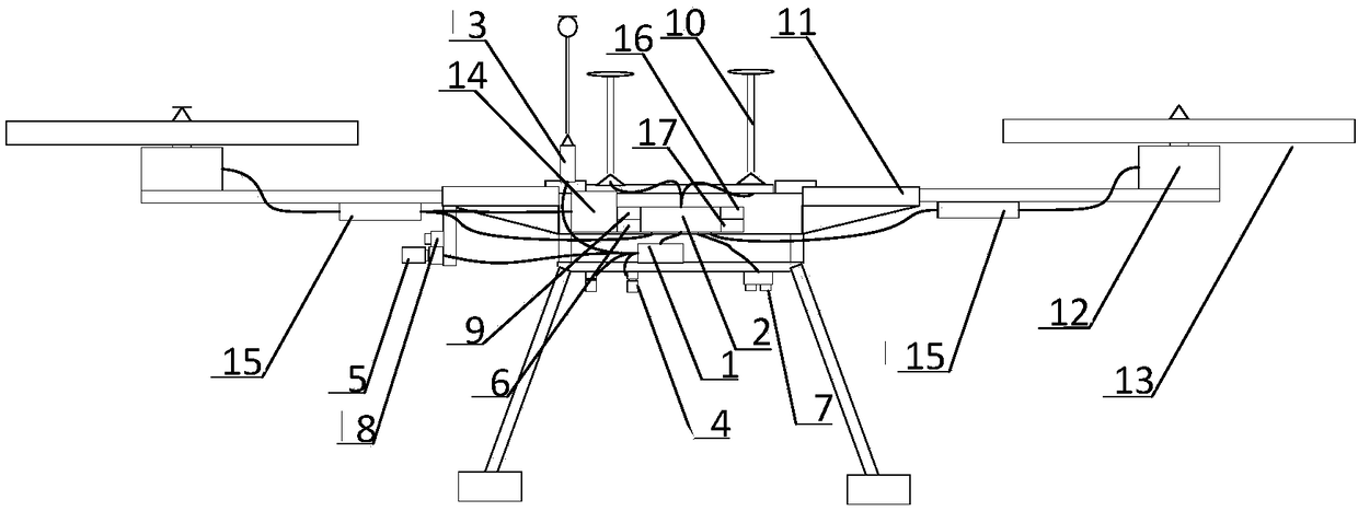
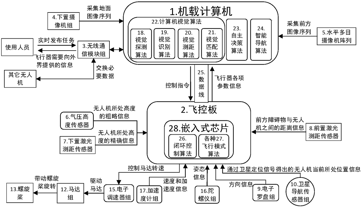
[0048] Such as Figure 1-4 As shown, an intelligent multi-rotor UAV based on an airborne computer includes an airborne computer 1, a flight control board 2, a communication module 3, a lower camera group 4, a horizontal multi-eye camera array 4, an air pressure altitude sensor 6, Lower laser ranging sensor 7, front laser ranging sensor 8, electronic compass group 9, satellite navigation sensor group 10, frame 11, motor group 12, propeller 13, battery pack 14, electronic governor group 15, gyroscope Instrument group 16 and accelerometer group 17.

[0049] Airborne computer 1, flight control board 2, communication module 3, lower camera group 4, horizontal multi-eye camera array 4, barometric altitude sensor 6, lower laser ranging sensor 7, front laser ranging sensor 8, electronic compass Group 9, satellite navigation sensor group 10, motor group 12, propeller 13, battery group 14, electronic governor group 15, gyroscope group 16 and accelerometer group 17 are all arranged on t...

Embodiment 2

[0073] A method for realizing an intelligent multi-rotor unmanned aerial vehicle based on an airborne computer, comprising the steps of:

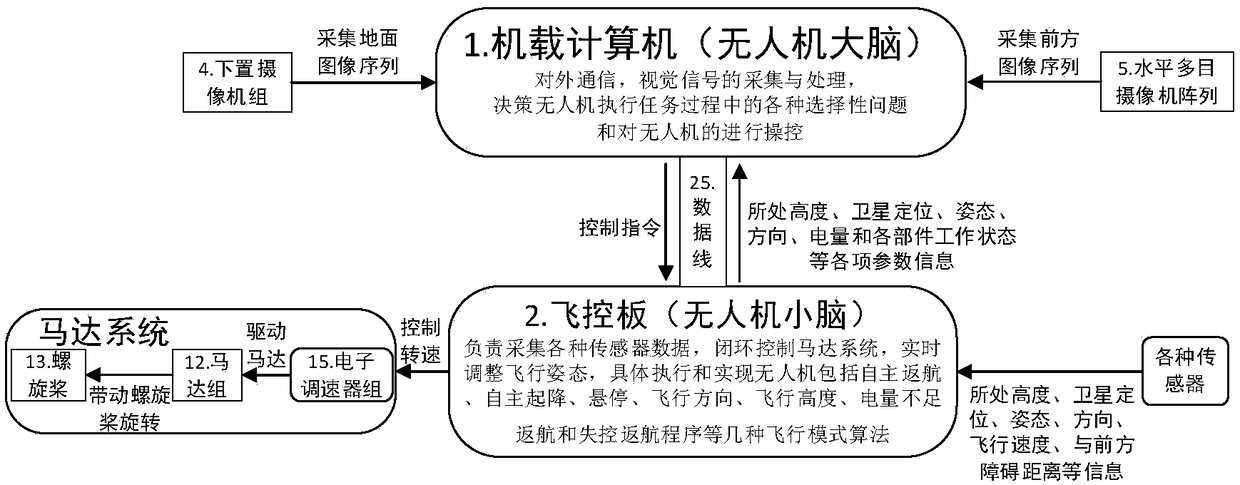
[0074] S1. The flight control board collects the real-time flight state parameter information of the UAV and sends it to the onboard computer. The flight state parameter information includes the current altitude information, the distance information between the obstacle in front and the UAV, and the current position. Several combinations or all of position information, attitude information, direction information, speed and acceleration information, power information and working status information of each component;

[0075] S2. The onboard computer collects visual signals including the ground image sequence and the front image sequence in real time, receives the real-time flight status parameter information sent by the flight control board, and communicates with the outside world in real time through the communication module;

[0076] S3. T...


PUM


Abstract

The invention discloses an intelligent multi-rotor UAV (unmanned aerial vehicle) based on a vehicle-borne computer and a realization method thereof. The intelligent multi-rotor UAV comprises a frame,a motor group, a propeller, a battery pack, a flight control board, a vehicle-borne computer and a communication module. The vehicle-borne computer collects a visual signal in real time and processesthe signal, receives real-time flight status parameter information sent by the flight control board, generates decisions and intelligent navigation and sends a control command to the flight control board. The vehicle-borne computer also communicates with the outside via the communication module. The flight control board receives the control command, carries out closed-loop control of the motor group, adjusting a flight attitude in real time, collects real-time flight status parameter information of UAV and sends the information to the vehicle-borne computer. The UAV and the realization methodare based on autonomy, a cerebrum and a cerebellum are separated, computer vision is used as a main external sensing tool, the severe dependence on traditional various UAV sensors, remote control methods and data long-distance transmission receipts are broken, thus the intelligent multi-rotor UAV has real independent intelligence features and work autonomously in an environment with very severe interference.

Description

technical field [0001] The invention relates to the technical field of unmanned aerial vehicles, in particular to an intelligent multi-rotor unmanned aerial vehicle based on an on-board computer and an implementation method thereof. Background technique [0002] Multi-rotor UAVs have been widely used in civilian fields due to their excellent maneuverability and take-off and landing characteristics. The board is used as the core of self-control; it is equipped with attitude, positioning and direction sensors; and it is operated by remote control. The difference is that the remote control distance and the convenience of operation of different aircraft are different. [0003] For example, patent application number CN201710488700.3, an intelligent drone control system is characterized in that it includes a remote controller for an intelligent drone and a flight controller installed on the intelligent drone, and the remote controller for the intelligent drone includes a remote co...

Claims


Application Information

Patent Timeline
Patent Type & Authority Applications(China)
IPC IPC(8): G05D1/10G05D1/08G01C11/02B64C27/08
CPCB64C27/08G01C11/02G05D1/0858G05D1/102
Inventor 郑宏远
Owner 郑宏远
Learn More