

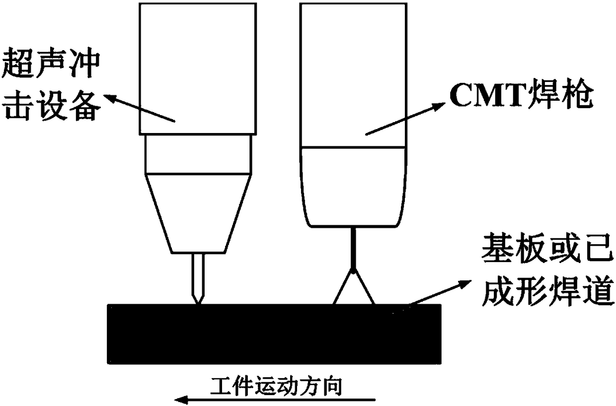
CMT-ultrasonic peening composite additive manufacturing method
An ultrasonic impact, additive manufacturing technology, applied in manufacturing tools, auxiliary devices, arc welding equipment, etc., can solve problems such as reducing the performance of metal additive manufacturing components, stress concentration, and reducing the effective bearing area of forming components
- Summary
- Abstract
- Description
- Claims
- Application Information
AI Technical Summary
Problems solved by technology
Method used
Image

Examples
Embodiment Construction
[0016] Further illustrate technical scheme of the present invention below in conjunction with specific embodiment:
[0017] The metal arc additive manufacturing experiment substrate involved in the present invention is aluminum alloy 6061, the substrate size is 300×150×4mm, and the welding wire is ER4043. The direct current cold metal transfer technology (cold metal transfer, CMT) was used to conduct the experiment of arc additive manufacturing of aluminum alloy. The CMT welding machine selected as the test equipment is the CMT Advanced4000 welding machine of Fonius Company.
[0018] Before the test, use a wire brush to remove the oxide film on the aluminum alloy substrate until the metallic luster is exposed, and use alcohol to clean the oil and dirt on the surface of the welding place within about 30-40mm. After the oxide film is removed, it should be cleaned within 2 hours. Welding is performed internally to avoid regenerating a new oxide film; set the welding parameters, ...
PUM
 Abstract
Description
Claims
Application Information