

Surface for reduced friction and wear and method of making the same
a technology of friction reduction and friction reduction, applied in the field of enhanced friction reduction surface, can solve the problems of excluding the treatment, reducing the tribological performance of the surface, so as to improve the tribological performance, and facilitate manufacturing.
- Summary
- Abstract
- Description
- Claims
- Application Information
AI Technical Summary
Benefits of technology
Problems solved by technology
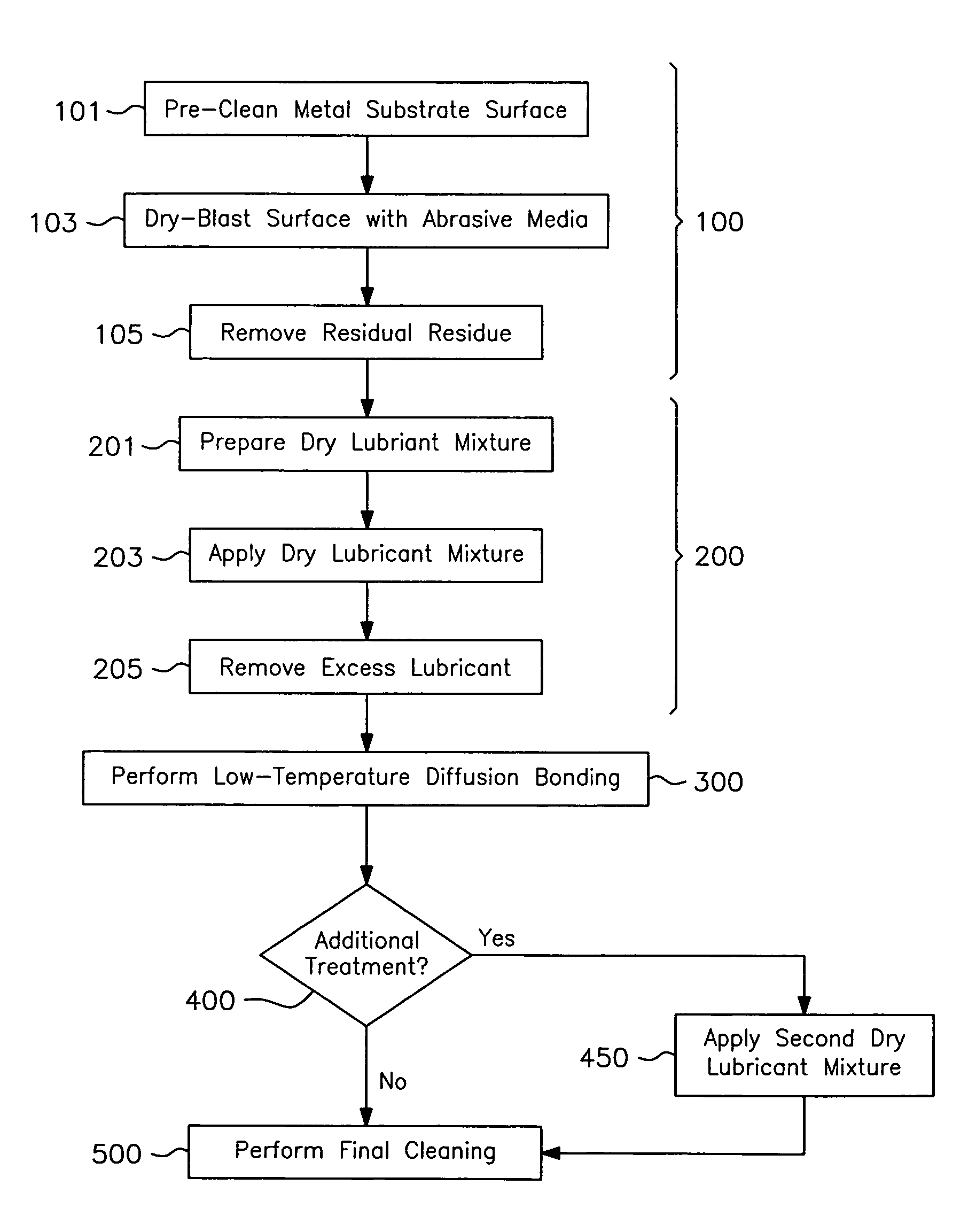
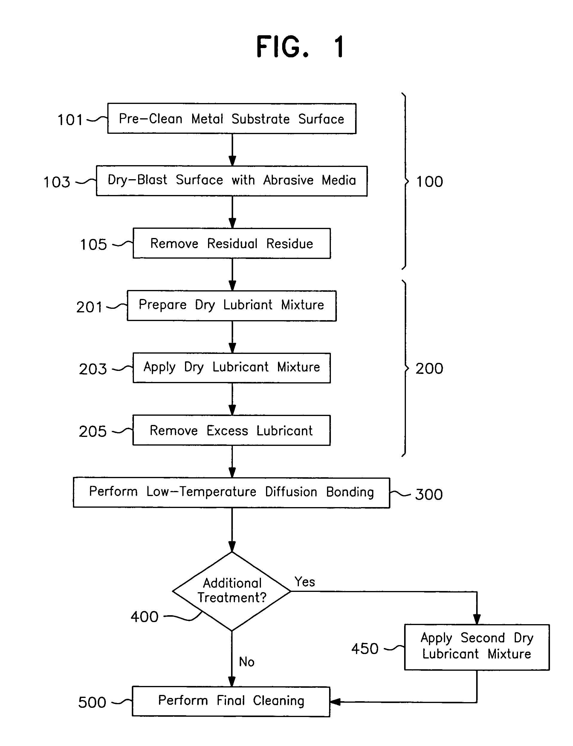
Method used
Image

Examples
example i
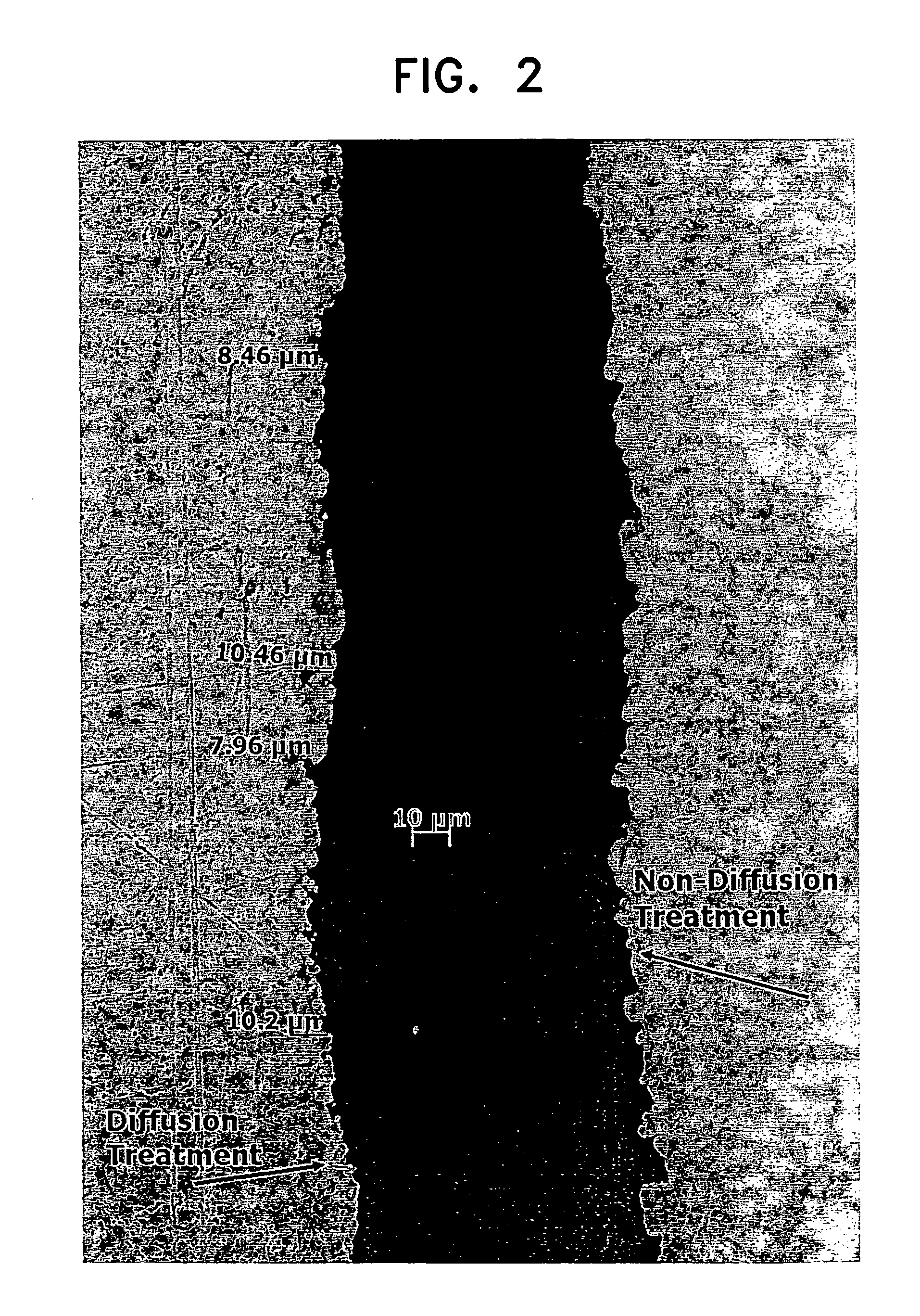
[0098]Penetration of the dry lubricant into the substrate matrix achieved through low temperature diffusion bonding was demonstrated through comparison with a substrate to which dry lubricant had been applied by impingement but without subsequent low temperature diffusion bonding.
[0099]More specifically, a 1 inch by 3 inch sample of 6061 aluminum was treated as follows. The sample was wiped clean and then treated with an aluminum oxide abrasive (size 30 grit at 70 psi). The sample was then blown off with high pressure air and processed by impingement with steel shot (size ES450) coated with a mixture of dry lubricant (MOS2 and PTFE), and applied at a pressure of 70 psi.
[0100]Upon completion of the impingement process, the sample was sectioned into two halves. The first half was set aside and did not undergo further treatment, while the second half was diffusion treated at 400° F. for a duration of four hours. (As the melting point of 6061 aluminum is 1142° F., the diffusion treatmen...
example ii
[0102]The overall dimensional effects of the low temperature diffusion bonding process on high precision metal were evaluated using two-½ inch and two-¾ inch cold drawn, turned ground and polished rounds (bars) of 4140 steel. The Ryerson specification for allowable variation in dimensional tolerances for both the M inch bar and the ¾ inch bar is 0.001 inches (Reference Specification from “Ryerson Stock List”, Joseph T. Ryerson and Son, Inc. Copyright 1995).
[0103]At the outset, ten dimensional measurements were taken along the length of each bar using a Laser Scan Micrometer having a measurement resolution of + / −0.000002 inches. Each bar was then processed in accordance with the present invention. Specifically, the bars were wiped clean and then treated with an aluminum oxide abrasive (size 30 Grit) at 40 psi. The bars were then blown off and subjected to inpingement using steel shot (size ES180) coated with a mixture of dry lubricant of MoS2 and PTFE and applied at a pressure of 70 ...
example iii
[0109]Tests were conducted to determine friction and operating temperature reduction obtained as a result of low temperature diffusion bonding. Testing was performed to ASTM standard G99 which measures the friction of a metal ball (pin) under an applied load (force) as it slides on a rotating disc. Two discs were tested, each with a corresponding ball (pin).
[0110]In this test, the balls (pins) used were ball bearings of Grade 25, AISI 52100 bearing steel (melting point 2595 degrees F.), hardness 62 (Rc) and surface roughness 2 Ra. The discs used were EN 31 (52100) bearing steel, with surface roughness 16 Ra. One disc did not undergo any treatment. The second disc was processed as follows.
[0111]The processed disc was wiped clean and then treated with an aluminum oxide abrasive (size 30 grit) at 40 psi. The disc was blown off with high pressure air and subjected to impingement using steel shot (size ES180) coated with a mixture of dry lubricant of MOS2 and PTFE and applied at a pressu...
PUM
| Property | Measurement | Unit |
|---|---|---|
| pressure | aaaaa | aaaaa |
| pressure | aaaaa | aaaaa |
| pressure | aaaaa | aaaaa |
Abstract
Description
Claims
Application Information