Shot peening machine for processing surface deformation strengthening treatment to magnesium alloy sample

A technology of surface deformation strengthening and shot blasting machine, which is applied in abrasive jetting machine tools, used abrasive processing devices, spray guns, etc. It can solve the problems of reducing the corrosion performance of magnesium alloys, the moving speed cannot be adjusted, and the spray gun cannot move horizontally. , to achieve the effect of ensuring concentricity and parallelism and preventing pollution

Inactive Publication Date: 2008-07-09
SHANGHAI AIERSI LIGHT ALLOY
View PDF2 Cites 34 Cited by
  • Summary
  • Abstract
  • Description
  • Claims
  • Application Information

AI Technical Summary

Problems solved by technology

As we all know, shot peening is a commonly used method to improve the fatigue strength and fatigue life of magnesium alloys. However, when shot peening the standard specimens of magnesium alloy shafts, there are still the following problems: 1. How to clamp the shafts for testing Sample? Second, the uniformity of the surface state of the sample after shot peening is an important indicator to measure the shot peening effect, so how to improve the uniformity of shot peening? Third, the impurities introduced in the shot peening treatment will reduce the corrosion performance of the magnesium alloy after treatment. How to prevent or reduce the contamination of the magnesium alloy sample by the impurities? Fourth, because the optimum shot peening intensity of magnesium alloy materials is small, it is difficult for conventional shot peening machines to meet the requirements. How to obtain the required shot peening intensity?
[0003] After searching the literature of the prior art, it is found that the Chinese invention patent number is 03822331.7, and the publication number is CN1681623. This patent provides a shot blasting device. The carrier

Method used


Image

  • Shot peening machine for processing surface deformation strengthening treatment to magnesium alloy sample
  • Shot peening machine for processing surface deformation strengthening treatment to magnesium alloy sample
  • Shot peening machine for processing surface deformation strengthening treatment to magnesium alloy sample

Examples


Embodiment Construction

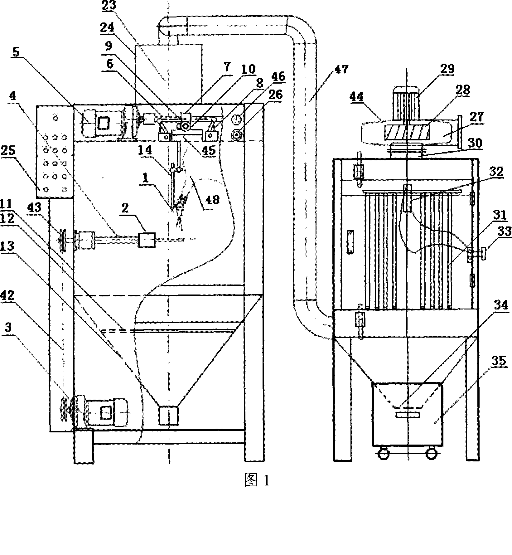
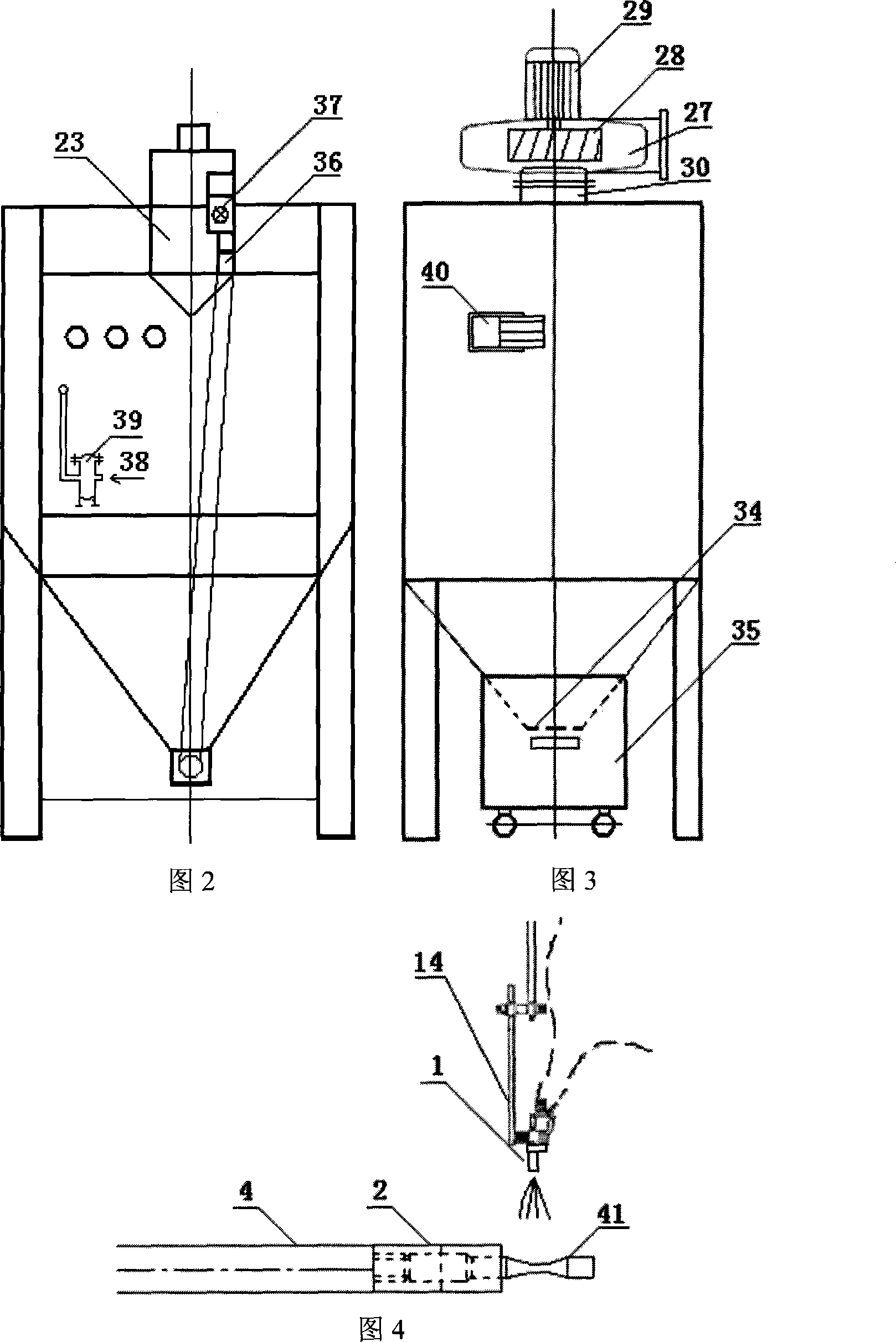
[0028] The embodiments of the present invention are described in detail below in conjunction with the accompanying drawings: this embodiment is implemented on the premise of the technical solution of the present invention, and detailed implementation methods and specific operating procedures are provided, but the protection scope of the present invention is not limited to the following the described embodiment.

[0029] This embodiment includes: main engine sandblasting system, upper cyclone separation system, dust removal system, air compression system, electrical system, wherein, the upper cyclone separation system is placed on the upper end of the main engine sandblasting system, and the lower part of the upper cyclone separation system is connected with the main engine sandblasting system. In the same way, the upper part of the upper cyclone separation system is connected with the dust removal system, and the dust removal system is placed outside the sandblasting system of ...


PUM


Abstract

The present invention relates to a device in the technical field of material processing, in particular to a peener which carries out the surface deformation strengthening process on magnesium alloy samples. The present invention comprises a main peening system, an upper whirlwind separation system, a dedusting system, an air compression system and an electric system, wherein, the upper whirlwind separation system is positioned on the upper end of the main peening system, the lower part of the upper whirlwind separation system is communicated with the main peening system, the upper part is connected with the dedusting system, which is positioned outside the main peening system, the air inlets of both the dedusting system and the main peening system are connected with the air compression system, and the electric system is connected with the main peening system, the upper whirlwind separation system, the dedusting system and the air compression system. The present invention can conveniently assemble and disassemble the samples of the shaft class, the range of the generated peening strenghth is wide, the effect and uniformity of peening is good, and moreover, pollution can be prevented.

Description

technical field [0001] The invention relates to a device in the technical field of material processing, in particular to a shot peening machine for performing surface deformation strengthening treatment on a magnesium alloy sample. Background technique [0002] Fatigue fracture has always been the most important form of damage to mechanical parts and engineering components. In aerospace, shipbuilding, chemical machinery, transportation, engineering machinery and other fields, about 50-90% of structural strength damage is caused by fatigue damage. Magnesium alloy is a metal material with great development potential, and the improvement of fatigue performance is conducive to expanding its application field. As we all know, shot peening is a commonly used method to improve the fatigue strength and fatigue life of magnesium alloys. However, when shot peening the standard specimens of magnesium alloy shafts, there are still the following problems: 1. How to clamp the shafts for ...

Claims


Application Information

Patent Timeline
IPC IPC(8): B24C1/10B24C3/04B24C3/22B24C5/02B24C5/06B24C7/00B24C9/00
Inventor 刘文才周阳张平
Owner SHANGHAI AIERSI LIGHT ALLOY
Why Eureka
Try Eureka